Ebers -Moll for computer/hand use
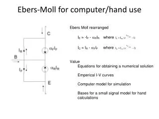
Ebers -Moll for computer/hand use . IC vs. VBE; VCS > 4 VT. NPN/ PNP – rce = 1/ gce. npn. pnp. I C vs. V CE. Early Voltage – r ce = VA/I CQ gm = I CQ /nVt rbe = /gm = nVt / I BQ Cbe = TF/rbe. Small Signal Model. I C vs. V VE - I C vs. V CE; . BJT Model.

Ebers -Moll for computer/hand use
E N D
Presentation Transcript
NPN/ PNP – rce = 1/gce npn pnp
IC vs. VCE Early Voltage – rce = VA/ICQ gm = ICQ/nVt rbe = /gm =nVt/IBQ Cbe = TF/rbe Small Signal Model
IC vs. VVE - IC vs. VCE; BJT Model CE Amplification ckt
Q pt Bias Stabilization Select IE RE = 4-5xVBEQ= 2.4V to 3V Ensures stability across process and temperature Given : ICQ = 2.5 mA, VCEQ = 6V, b = 100, & IBQ = 25uA, VA = 50 V, VCC = 10 V BIAS RESISTORS: RB1 = 14 K ohms, RB2 = 6 K ohms, & RE = 2.4V/2.5mA 1 K ohms Small Signal result : rbe = nVt/IBQ = 26mV/25uA 1 K ohms, gm = ICQ /nVt 40 x 2.5mS = 100 mS, rce =VA/ICQ = 50/2.5mA = 20 Kohm
f1 or High Pass Bias Considerations FindCc1, Cc2, & CE Using Amplification Mid-Band BIAS RESISTORS: RB1 = 14 K ohms, RB2 = 6 K ohms, & RE 1 K ohms Small Signal result : rbe = nVt/IBQ = 26mV/25uA 1 K ohms, gm = ICQ /nVt 40 x 2.5mS = 100 mS, rce =VA/ICQ = 50/2.5mA = 20 Kohm CE- Amplification
Mid-band and f2gain Cc1, Cc2, and CE were selected to be short circuits at mid-band and higher Resulting in the following small signal model CE- Amplification Mid-Band Output Eq Input Eq Input Eq Simplified
f2 Considerations Amplification CE- Amplification At midband A = CL and Cbe neglected At f2 A = solve for poles For a midband gain of -10; RC = -10/-gm = 10/.1mS = 100 ohms;
Bias Check For a midband gain of -10; RC = -10/-gm = 10/.1mS = 100 ohms; RC sets gain RESISTORS: RC = 100 ohms, RB1 = 14 K ohms, RB2 = 6 K ohms, & RE 1 K ohms; Stabilzes Qpt, RB1 AND RB2 Set VBB. • VCE = VCC – IC{RC+ RE} = 10 – 2.5mAx1.1K ohms = 7.25V • VCE = 7.25V • VRE = 2.5V = Emitter voltage • VB = 0.65V + 2.5V = 3.15V = Base Voltage • ZL = O-scope probe in lab • CC1 = ??? • CC2 = ??? • CE = ???