Electronics
Electronics. Circuits. Current. Current Electricity. Current electricity is a movement of charge , in most cases the particle carrying the charge is an electron . Electrons have a negative charge. When a charge is put into motion by a chemical reaction it is contained in a cell .

Electronics
E N D
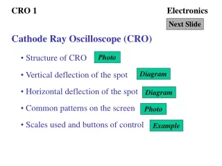
Presentation Transcript
Electronics Circuits
Current Electricity Current electricity is a movement of charge, in most cases the particle carrying the charge is an electron. Electrons have a negative charge When a charge is put into motion by a chemical reaction it is contained in a cell. The mild push on electrons is produced in a cell that is contained in 1.5 V
Battery Battery is short for battery cellsTo make a 9V battery, you need 6 cells, each producing 1.5 V of potential all attached in a seriesTake apart a 9V battery and you will find 6 cells inside
Alternative Power Sources Without the voltage source, there will be no current flowing. All sources of electricity convert something called potential energy to kinetic energy. Potential energy is waiting to be used Kinetic energy is being used.
What if you keep adding more batteries (cells)? Adding more cells The current in a series circuit depends upon the number of cells. The more cells, the greater the current Current is not used up Current is the same everywhere in a series circuit, even if it has lots of lamps or other components.
Terminals Connect a wire from one terminal to the other, the energy flows from the negative terminal to the positive terminal, • Two connectors on the battery are called Terminals • A positive terminal and a negative terminal • When one terminal of a battery is connected with a conductor to the other terminal of a battery, a circuit results.
A circuit is an unbroken loop of conductive material that allows electrons to flow constantly
http://www.allaboutcircuits.com/vol_1/chpt_1/3.html Any break, Anywhere in a circuit prevents electron flow throughout the circuit.
Electric circuits The bulb will only light if there is a battery and a complete circuit We usually add in a switch to the circuit, so that we can break the circuit and stop the electric current when we want to.
Amps Current is the measure of how much electric charge flows through a circuit. The more charge that flows the bigger the current Current is measured in units called amps. The symbol for Amps is “A”. A device called an ammeter is used to measure current. You must connect the ammeter in SERIES with the circuit.
What makes a circuit http://www.andythelwell.com/blobz/guide.html
http://www.youtube.com/watch?v=3RzN7T5xpVc SchoolHouse Rock Electricity, Electricity!
We use circuit symbols to draw diagrams of electrical circuits, with straight lines to show the wires. This diagram shows a CELL not a battery
Circuit Diagrams Always make the wires straight lines If you have to draw a circuit diagram from scratch, it is usually easier to draw the circuit symbols first, and then add all the wires.
The lamp will light when one wire is connected to one battery terminal and the other wire is connected to the other terminal. There is only one way to connect it to a battery to produce results. Two or more lamps, however present a new set of challenges.
Circuits consisting of just one battery and one load resistance are very simple to analyze, but they are not often found in practical applications. Usually, we find circuits where more than two components are connected together. There are two basic ways in which to connect more than two circuit components: series and parallel.
Series Circuits 2/10/11
Explanations of Ideas http://lgfl.skoool.co.uk/content/keystage3/Physics/pc/learningsteps/SPCLC/launch.html
Series Circuit In a series circuit, all components are connected end-to-end, forming a single path for electrons to flow.
Series Circuits If you put more lamps into a series circuit, the lamps will be dimmer than before. In a series circuit, if a lamp breaks or a component is disconnected, the circuit is broken and all the components stop working.
Simple Circuit Current in a Simple Circuit -- Current is defined as the flow of electricity through a circuit over time. Power in a Simple Circuit -- power is the product of current and voltage.
Two Categories A parallel circuit is one of the two basic types of electric circuit that can be found in electrical devices. In a parallel circuit, however, there are multiple pathways between the circuit’s beginning and end. As a result, since the current has more than one route to take, the circuit can still function if one path fails. This makes parallel circuits much more fail-resistant than series circuits which is why parallel circuits are common in everyday applications, such as household wiring.
Regardless of how many different paths the circuit has, the total voltage stays the same, and all components of the circuit share the same common points. • This set of common points: • One thing to consider about parallel circuits is the current load that they carry. • When a circuit has multiple paths for current, the circuit's resistance drops.
Voltage does not change, this means the current has to increase its speed. (Ohm’s law) • Thus, the more paths that a circuit has, the greater the current flow • Parallel circuits are found in virtually all complex electrical devices.
Measuring Parallel Circuits • Testing in a parallel circuit using a voltmeter or multimeter, which tests multiple measurements • Measure in parallel with the circuit • Multiple branches means the load is distributed over more than one path, and measuring only one path will not present the full picture.
Parallel Circuits In parallel circuits different components are connected on different branches of the wire. In a parallel circuit, if a lamp breaks or a component is disconnected from one parallel wire, the components on different branches keep working. The lamps stay bright if you add more lamps in parallel.
In a parallel circuit, all components are connected across each other, forming exactly two sets of electrically common points.
And each additional bulb will glow brightly until the total burden exceeds the ability of the cells.
Parallel Circuits When all the devices are connected using parallel connections, the circuit is referred to as a parallel circuit. In a parallel circuit, each device is placed in its own separate branch.
When arriving at the branching location, a charge makes a choice where to travel through on its journey back to the low potential terminal.
Tollway Analogy A tollbooth is the main location of resistance to car flow on a tollway. Adding additional tollbooths within their own branch on a tollway will provide more pathways for cars to flow through the toll station. These additional tollbooths will decrease the overall resistance to car flow and increase the rate at which they flow.
As the total current exits the negative (-) battery terminal and travels through the circuit, some of the flow splits off . Like a river branching into several smaller streams, the combined flow rates of all streams must equal the flow rate of the whole river.
The same thing is encountered where the currents through to the flow back to the positive terminal of the battery (+) This is the second principle of parallel circuits: the total circuit current is equal to the sum of the individual branch currents. Finally, applying Ohm's Law to the rightmost ("Total") column, we can calculate the total circuit resistance
More current flows through the smaller resistance. (More charges take the easiest path.) The battery or source is represented by an escalator which raises charges to a higher level of energy. By the time each charge makes it back to the battery, it has lost all the electrical energy given to it by the battery. The total of the potential drops of each "branch" or path is the same as the potential rise across the battery. This demonstrates that a charge can only do as much work as was done on it by the battery.
The charges are positive so this is a representation of conventional current(the apparent flow of positive charges) The charges are only flowing in one direction so this would be considered direct current ( D.C. ).
Parallel Circuit Current in a Parallel Circuit -- Current is a function of voltage and resistance. Power in a Parallel Circuit -- In parallel circuits, power is a function of current and voltage.
http://www.bbc.co.uk/schools/ks3bitesize/science/energy_electricity_forces/electric_current_voltage/revise5.shtmlhttp://www.bbc.co.uk/schools/ks3bitesize/science/energy_electricity_forces/electric_current_voltage/revise5.shtml Voltage Voltage is a measure of the difference in electrical energy between two parts of a circuit. The bigger the difference in energy, the bigger the voltage. Voltage is measured in volts. The symbol for volts is V. For example, 230V is a bigger voltage than 12V.
Measuring voltage Voltage is measured using a voltmeter. Some types of voltmeter have a pointer on a dial, but most have a digital readout. To measure the voltage across a component in a circuit, you must connect the voltmeter in parallel with it. Using a voltmeter to measure the voltage across a lamp You can measure the voltage across a cell or battery. The more cells, the bigger the voltage. The more cells, the bigger the voltage
Ohms Law Ohm's Law defines the relationships between (P) power, (V) voltage, (I) current, and (R) resistance. One ohm is the resistance value through which one volt will maintain a current of one ampere.
( I ) Current is what flows on a wire or conductor like water flowing down a river. Current flows from negative to positive on the surface of a conductor. Current is measured in (A) amperes or amps. ( V ) Voltage is the difference in electrical potential between two points in a circuit. It's the push or pressure behind current flow through a circuit, and is measured in (V) volts. ( R ) Resistance determines how much current will flow through a component. Resistors are used to control voltage and current levels. A very high resistance allows a small amount of current to flow. A very low resistance allows a large amount of current to flow. Resistance is measured in ohms. ( P ) Power is the amount of current times the voltage level at a given point measured in wattage or watts.