Revisions
370 likes | 590 Views
Revisions . There is a column with dates that the plans were revised in the bottom right corner of the title sheet. Approval Signatures . John Hancock.

Revisions
E N D
Presentation Transcript
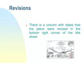
Revisions • There is a column with dates that the plans were revised in the bottom right corner of the title sheet.
Approval Signatures John Hancock • In the extreme lower right hand corner there is a table containing signatures of authorization. Note especially the signatures under APPROVED FOR RIGHT OF WAY ACQUISITION and APPROVED FOR CONSTRUCTION. Plans should not be used to acquire right of way or for construction without checking to make sure that the appropriate signatures are present. • The absence of appropriate signatures means that the plans have not been authorized for right of way acquisition or construction and a note should be on the sheet stating that the plans are not authorized for right of way acquisition or construction.
Location Map • The purpose of the location map is to orient the project in relation to existing highways or to natural or man-made terrain features in the area. • As a general rule, LOCATION MAPS are oriented to the NORTH. This will not always be the case. Locate the compass arrow; it will always indicate the northerly direction. • The following symbols are used on highway maps to indicate types of roads: • U.S. Routes: N
Symbols • State Primary Highways: • State Secondary Roads: • Interstate Highways: • Forestry Roads:
PLAN & PROFILE • Here you see the Plan view, Profile view and the END view or CROSS SECTION.
PLAN • Looking at the PLAN VIEW, imagine looking straight down on the project from a point directly above.
What is shown on a Profile Sheet? Profile Sheet
PROFILE VIEW • The PROFILE VIEW is like a SIDE VIEW as if you are standing off to one side of the road and looking back at the road.
Stationing • Stationing is the process of defining locations along the project by station numbers. Highway construction projects are divided into reference points spaced along the project. These points are called STATIONS and are designated by a number such as 755+50.00. • Later we will see you how to relate this number to a location along the project.
Plan sheets may look complicated however they are not. Lets look at what is on a plan sheet. Plan Sheet
Plan Sheet • On the plan sheet is a line running down the center of the proposed highway. This line represents the BASELINE with the symbol: • The BASELINE is the basic reference point used for all horizontal measurements. • Follow this BASELINE and you will notice regularly spaced marks. Every fifth (5th) mark goes through the baseline and there are four other marks equally spaced between these marks that do not go through the baseline. These shorter marks are on the left side of the BASELINE as you look up station (i.e. from station 1755+00 to 1760+00). • These marks indicate STATIONS along the baseline that are based on a reference point which may, or may not, be on this particular project. For this reason, it is not uncommon to see a project begin with a number that is quite high, not zero as you might expect.
Baseline • Numbers such as 1755 and 1760 are directly above or below the lines that cross through the baseline and indicate a distance of 500 feet between each of these. • Between these stations are stations one hundred (100) feet apart and depicted as follows: • 1. How many stations are there between 1755+00 and 1761+00? _______________ • Any point between stations is written as station number (+) feet, such as 1755+80.
Baseline • 2. What is the station number for Point A?__________________. • A station number is read as follows: • 130+02: Station one thirty plus zero two (meaning 2 feet AHEAD of station one thirty). • 130+00: Station one thirty plus zero, zero (meaning exactly at station one thirty).
Station Numbers • NOTE: The word NAUGHT is sometimes used instead of zero, or "0" Thus, the above stations might be read this way: • 130+02: Station 130+ naught, two. • 130+00: Station 130 + naught, naught. • When you take the plus (+) sign out of a station number such as 134+50, you have the value of the number in actual feet. • Example: 134+50=13,450 or • 134 x (100) + 50 = 13,400 + 50 = 13,450
DISTANCE • To calculate the DISTANCE (or points between stations) subtract the lower station from the higher station. • For example, to calculate the distance from sta. 134+50 to sta. 132+80, you would delete the (+) sign and subtract in this way: 13450 13280 170 • OR, you may want to figure it this way: • from sta. 132+80 to sta. 133+00 is 20 ft • from sta. 133+00 to sta. 134+00 is 100 ft • from sta. 134+00 to sta. 134+50 is 50 ft • Therefore, we have a total of 170 ft • 3. What is the distance from Point A to station 130+80? ____________________
DISTANCE • 3. What is the distance from Point A to station 130+70? ____________________
North, South, East, West • Observe which way the station numbers increase. Looking again at the Plan Sheet, find the compass arrow. Notice that the station numbers normally increase from WEST to EAST. On highways that are oriented to the north or south, station numbers normally increase from SOUTH to NORTH. • Remember: WEST to EAST and SOUTH to NORTH.
Baseline Location During Construction • Wooden stakes with the station numbers written on them are driven into the ground early in the construction process to orient construction personnel. • These stakes will be moved later to the side of the roadway as construction progresses in order to maintain points for reference. • The distance from the baseline will also be written on these stakes. • Any point on a project may be located on the ground or on the plans by the station and the distance left or right of the baseline. Locations of right of way points or proposed easements are located and labeled using this method.
AHEAD and BACK • The word AHEAD is used to denote the direction in which the project is going. This is indicated by increasing station numbers; the word AHEAD is not found on the plans. • The word BACK is used to denote the opposite direction and is indicated by decreasing station numbers; it is not found on the plans.
AHEAD and BACK • LEFT or RIGHT relates to facing AHEAD on a project. These words are also not on the plans • Locate point on the plan below. You will find it 200 ft to the right of the baseline at station 755+50. • The "highway address" is: Station 755+50, 200 ft RT. of the baseline.
AHEAD and BACK • 4. From this plan, give the "highway address” (location) of point . • 5. Is this point AHEAD or BACK of sta. 761 + 42______________?
CURVES • A CURVE is defined as any section of roadway in which the points along the baseline do not fall on a straight line or tangent. • On a horizontal curve, the roadway bends to the right or left. • On a vertical curve, the road bends up or down. • There are two kinds of horizontal curves: Circular and Spiral
CIRCULAR & SPIRAL CURVES • A circular curve would make a complete circle if it kept going around. A spiral curve would keep getting smaller and smaller if it kept going around. In order to approximate the path a vehicle makes when entering or leaving a circular horizontal curve, a spiral transition curve will be provided for horizontal curves with a radius less than or equal to 2865 feet, except for interchange ramps and loops.
SPIRAL CURVES • A spiral is simply a transition from a tangent section (with an infinite radius) to a curve having a defined radius. Spirals are needed because all vehicles follow a transition path when entering or leaving a horizontal curve because the changes in steering and centrifugal force cannot be accomplished instantly. On sharp curves (without spirals) at high speeds where this transition path is significantly longer, the driver tends to encroach on the adjoining traffic lanes and/or reduce speed, signifying a reduction in driver comfort. Spirals make it easier for the driver to maintain control of the vehicle while negotiating these curves at a uniform speed. Volume 2 of the Road Design Manual contains figures and an explanation of Spiral Curves and Transition (Spiral) Curves in metric.
This drawing depicts two horizontal curves. • The Curve to the Left starts at the Point of Curve, PC station 187+50.50 and goes to the Point of Reverse Curve, PRC station 190+23.45. • The Curve to the Right starts at this PRC and goes to the Point of Tangent, PT at 193+76.74 where a tangent begins. LS=160ft V=27mph E=0.08 LS=180ft V=36mph E=0.08
LS=160ft V=27mph E=0.08 • Direct your attention to the curve to left. Directly above it, or to the inside of the curve, you will note a series of numbers and symbols which together make up the CURVE DATA. • Now for an explanation of each symbol: • The POINT OF CURVATURE (PC). This is where the baseline leaves the tangent and begins to form a curve. LS=180ft V=36mph E=0.08
LS=160ft V=27mph E=0.08 • The intersection of the tangents is the POINT OF INTERSECTION (PI). • This is much like a corner on a city street system. • It is obvious that such corners are impractical on high-speed highways; therefore, we construct curves. LS=180ft V=36mph E=0.08
LS=160ft V=27mph E=0.08 • Whether a highway is curving LEFT or RIGHT depends on which side of the baseline the PI is located. • If the baseline is located on the right side of the PI, the CURVE is to the RIGHT. • If the baseline is to the left of the PI, the CURVE is to the LEFT. LS=180ft V=36mph E=0.08
HORIZONTAL ALIGNMENT • The baseline of the road is controlled by the terrain features around it. • The highway curves around such terrain features as hills and lakes and it stretches out in straight lines (tangents) through the level valleys. • Such a series of straight lines and curves is called the HORIZONTAL ALIGNMENT. • This alignment can be recognized by looking at the Plan View of the highway.
LS=160ft V=27mph E=0.08 • On the CURVE DATA, for the curve to the right, is a designation PT which means POINT OF TANGENT. • This is the station where the curve ends and the tangent (straight line) begins. LS=180ft V=36mph E=0.08
LS=160ft V=27mph E=0.08 • In addition to designations PRC, PC, PI & PT, you will often find the designation POC. • This refers to a POINT ON THE CURVE. • This point can be any point on the curve where some information is necessary. • Usually it is a point where two baselines intersect, therefore, serving as a reference to the tie-in point for connecting roads. LS=180ft V=36mph E=0.08
LS=160ft V=27mph E=0.08 • The designation POT (POINT ON THE TANGENT) will frequently be found. • It too has no relative position in regards to anything other than itself, but serves to pinpoint some special information. LS=180ft V=36mph E=0.08
Check the notations on this plan and note that the original baseline for the connection at sta. 713+40.78 was a POC (Point on the Curve); however, subsequent revisions placed the actual connection to a POT (Point on the Tangent) at sta. 712+65.23. LS=160ft V=20mph E=0.08
Sometimes during construction, stakes are moved or knocked out. In the upper left hand corner of this plan you will find a diagram of survey data used to relocate particular points along the roadway in the event marking stakes are moved. • This particular reference pinpoints the Point of Intersection (PI) at sta. 714+07.83. An explanation of survey data will be covered later in this guide. LS=160ft V=20mph E=0.08
6. Using this plan, (a) locate and give the station number of the PC _____________, and (b) indicate which way the curve bends_________. LS=160ft V=20mph E=0.08