Download
1 / 23
230 likes | 380 Views
The design of hybrid systems poses significant challenges, integrating varied aspects such as data, behavior, and architecture across multiple engineering disciplines. Modern software engineering methods advocate for visual specifications, yet a formal foundation is crucial to avoid ambiguities. This paper presents a modular visual model for hybrid systems, focusing on an electronic height control system as a case study. We explore how hierarchical graphs and related models can formalize both the structure and behavior of hybrid systems, facilitating enhanced verification and optimization processes.

E N D
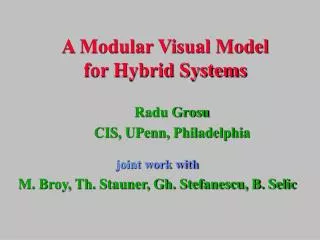
A Modular Visual Model for Hybrid Systems Radu Grosu CIS, UPenn, Philadelphia joint work with M. Broy, Th. Stauner, Gh. Stefanescu, B. Selic
Motivation • The design of hybrid systems is a difficult task. One has to consider many different aspects like data, behavior, architecture and distribution. • Moreover it usuallyinvolves people from different engineering disciplines. • Many modern SE methods like UML, ROOM and SDL recommend the use of visual specifications. • A formal foundation is needed however, to prohibit ambiguities which may be fatal in this context.
Overview • Anelectronic height control system (BMW). • Thecomputation model. • Hierarchic graphs andtheirassociatedmodels. • Conclusions.
Electronic Height Control System • Whenever the chassis level is outside of a tolerance interval it has to be increased or decreased to get close to the center of the interval. • Very short deviations from the tolerance interval should not be compensated. • After a compensation, some time should pass before the actuatoris switched on again. • The chassis level may not be modified whenever thecar is going through a curve.
Filter D EHC Architecture bend aHeight sHeight fHeight dReset reset EHC +
EHC Architecture bend aHeight Control sHeight fHeight Filter D dReset reset EHC
sHeight fHeight aHeight dReset time t t´ t´´ Typical Evolution of the EHC
control b2o outBend b2o o2b inBend a_const Top Level of the Control Component
outBend i2u i2u control inTol outTol i2d a_const outBend reset reset o2b b2o o2b b2o inBend a_const The State OutBend
control outBend i2u inTol outBend outTol i2d a_const reset o2b b2o o2b b2o inBend a_const i2u i2d outTol up down a_inc a_dec u2i u2i d2i reset The State outTol
Nodes and Arcs Graph = a set of nodes connected by a set of arcs Node interface = set of incoming/outgoing arcs a b N - arcsa denote types - nodesN denote relations
A C n1 n2 n1 n2 n1 B1 B2 B A A A A B A A A B A identification ramification transposition Graph Construction Primitives Operators on nodes A1 A2 A B C visual attachment sequential composition feedback Connectors A A identity
Role of Visual Attachment n2 n1 n2 n1 Operators on nodes A1 A2 A * C A B C n1 B1 B2 * B visual attachment sequential composition feedback Connectors A A A A A B A A A A B A identity identification ramification transposition
Control-flow model Data-flow model n2 n1 n2 n2 n1 n1 n2 n1 Control- and Data-Flow Models
Control-flow model Data-flow model A A C C n1 n1 B B Visual Attachment and Feedback
Additive Interpretation • An additive graph describes control flow: • control resides in only one node • control rec/sent on only one interface point • control paths forward control between nodes • Intended disjointness of nodes and interfacepoints achieved by: • interpreting * by the disjoint sum +
Multiplicative Interpretation • A multiplicative graph describes data flow: • control is in all nodes • data is sent/rec on all input/output ports • channels forward the data between nodes • Intended parallelism of nodes and ports is achieved by: • interpreting * by the product x
Nxt Ana Out Lim The Hybrid Machine ... Act1 Actn Ana
D Architecture Specification bend aHeight sHeight Ctrl fHeight Filter reset dReset EHC
guard1 ex1 body1 exit action1 en1 entry LeafNode enm guardn exn entry exit bodyn action1 wt ~guard wt sub nodes N1..Nk guard1 ex1 body1 exit action1 en1 entry CompNode enm guardn exn entry exit bodyn wt1 wt1 action1 wtj wtj Leaf and Composed Nodes
The Discrete Machine Nxt Nxt Register Ana Out Out Lim clock
Tightening Sliding A A A m m A C C C B B = = m n n D D D n C n p p m D B E E B Two Feedback Laws
Conclusions • HyACharts allow the hierarchical specification of the structure of a hybrid system. • Subsystemsmay be described with other formalisms. • HySCharts allow the hierarchical specification of the behavior of a hybrid system. • Both discreteand continuous aspects are integratedin a uniform way (activities, preemption, entry/exit actions). • HyACharts and HySCharts are dual models of hierarchic graphs. Theirformal theory allows their verification and optimization.