Comprehensive Guide to Rational Software Modeler: Diagrams, Setup, and Archiving
This tutorial provides a detailed walkthrough for setting up the Rational Software Modeler (RSM) environment, integrating it with Eclipse, and utilizing various UML diagrams such as Activity, Use-Case, Class, and Sequence diagrams. Learn how to create models, add components, establish relationships, and visualize processes related to system interactions and design. Additionally, discover archiving techniques to share and transfer projects effectively among team members, ensuring smooth collaboration and submission.

Comprehensive Guide to Rational Software Modeler: Diagrams, Setup, and Archiving
E N D
Presentation Transcript
Rational Software ModelerTutorial Pongtip Aroonvatanaporn
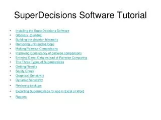
Outline • Setting up RSM environment • Activity Diagram • Use-case Diagram • Class Diagram • Sequence Diagram • Archiving
RSM Environment • Built on Eclipse environment • Workspace • Modeling perspective • Comes with Eclipse 3.2 • Or installed as Eclipse plug-in • Note: on Windows 7, use your own version of Eclipse and JDK/JRE • Download Eclipse 3.2.2 and latest JDK/JRE • Choose “Extend Eclipse”
Activity Diagram • Captures a sequence of activities and actions • In CSCI577, used to model business workflow or business process
Components • Partitions • Actions • Control node (i.e. decision node) • Control flow • Transfer of action • Object node (i.e. data) • Object flow • Transfer of object
Steps • Create a new model called “Activity Model” • Right click on the model • Add Diagram Activity Diagram • On the right panel, select the following • Partition • Actions • Control node (decision node) • Control flow
Use-Case Diagram • Captures the interaction between actors and system • Shows the possible capabilities/functionalities the system can perform • Association • Roles and multiplicities do not apply
Components • Actor • Show the hierarchy of users • Use-case • The actions that user can perform • Relationships • Association • Dependencies • “Includes” • invocation of a use case by another one • “Extends” • Ultimately an alternate course of action • Should avoid as it complicates the model
Steps • Create “System Analysis” model • Right click on the model • Add Diagram Use-case Diagram • Add an actor • Add a few use-cases • Association from actor to use-case • “Include” relationship from 1 use-case to another • Right vs. wrong • User inheritance (super user)
Class Diagram • Detailed designs of the classes • Contains • Attributes • Operations • Relations between classes
Components • Classes • Boundary: pages, view • Controller: logic • Entity: model, data • Relationships • Association: “Has-a” • Aggregation: “Part-of” • Composition • Stronger aggregation • Lives and dies with parent
Steps • Create a new model called “Design Model” • Create a package called “Design Classes” • Add new classes: • <<boundary>> VolunteerPage • <<controller>> TimeController • <<entity>> Time • <<entity>> TimeSheet • <<entity>> VolunteerProfile • Create relationships • Composition • Specialization • Association
Sequence Diagram • Captures the detailed sequence of operations when a use-case takes place • Includes: • Actors • Components • Classes • Hardware • Software
Steps • Create a package called “Sequence” • Right click on the model • Add diagram Sequence diagram • Sequence diagrams are part of “collaboration”. Each collaboration should be named according to the use-case • Different ways of creating “life-line” entity • Select from existing • Create new object • Unspecified (defined later by drag and drop)
Archiving • Archiving the model to be transferred to different computers • Share among team members • Submission • Export as a RAS Asset
Steps • Go to File -> Export • Choose RAS -> RAS Asset • Choose the location to save the file • Choose the project to export • Make sure that the option “Export as complete Eclipse project” is checked