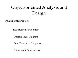
UML2 Composite Structure Diagrams: Modeling Internal Structure
180 likes | 253 Views
Learn how to represent the internal structure of a classifier using composite structure diagrams in UML2. Explore the use of parts, ports, and connectors to show detailed information not visible on other diagrams.

UML2 Composite Structure Diagrams: Modeling Internal Structure
E N D
Presentation Transcript
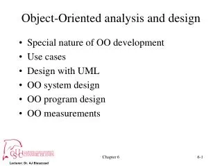
Object-Oriented Analysis and Design with UML2 and Rational Software Modeler 04. Other UML Diagrams
The Taxonomy of Diagrams in UML 2.1
New in UML2 Composite Structure Diagrams • A composite structure diagram can be used to represent the internal structure of a classifier, for instance a class • Allows to show details otherwise not visible on other diagrams, as illustrated in the following example: • External structure of the classifier described using ports, “collection points” for the classifier’s provided and required interfaces • Internal structure shown using parts and connectors in the structurecompartment (see example next slide) or in a structure diagram Same class diagram describes multiple implementations!
Example of a Composite Structure Diagram Parts Ports
Revised in UML2 Components • Definition of a component: • Specifies a formal contract of the services that it provides to its clients (provided interfaces) and those that it requires from other components or services in the system (required interfaces) • Can be replaced at design time or run-time by a component that offers equivalent functionality based on compatibility of its interfaces • Components can be used to: • Provide a high-level, architectural view of the system • Represent the logical components that will be running on the physical systems Three views of the same component
Example of a Component Diagram The structure diagram of the Store component
Subsystems • A subsystem is a specialized version of a component, but it does not add anything to it • The decision to use a subsystem vs. a component is up to the methodology of the modeler • Subsystems are often equated to larger components • Component stereotyped <<subsystem>> • Note: There are other pre-defined UML2 component stereotypes (e.g. <<implement>>, <<specification>>, <<process>>, <<service>>)
Artifacts • An artifact is the specification of a physical piece of information that is used or produced by a software development process, or by deployment and operation of a system • Examples: source files, scripts, and binary executable files • Standard UML stereotypes: <<document>>, <<executable>>, <<file>>, <<library>>, <<script>>, <<source>> • The physical rendering of one or more model elements by an artifact is shown with a <<manifest>> dependency • May be further stereotyped (e.g. <<tool generated>>) • Artifacts may have composition associations to other artifacts that are nested within it
Deployment: Nodes and Communication Paths • A node is computational resource upon which artifacts may be deployed for execution • Examples: application server, client workstation, mobile device, embedded device • Nodes can be connected to represent a network topology by using communication paths • Specific network topologies can then be defined through links between node instances • Hierarchical nodes (i.e., nodes within nodes) can be modeled using composition associations, or by defining an internal structure
Deploying Artifacts • A deployment is the allocation of an artifact or artifact instance to a deployment target • A deployment specification can be used to specify the execution parameters of a component artifact that is deployed on a node Two equivalent visual representations of the deployment of artifacts to a deployment target (including e dependency between the artifacts)
Deployment: Execution Environments • An Execution Environment is a node that offers an execution environment for specific types of components that are deployed on it in the form of executable artifacts • Examples: OS, workflow engine, database system, J2EE container • Execution Environment instances are assigned to node instances by using composite associations (the Execution Environment plays the role of the part) • Execution Environments can be nested (e.g., a database Execution Environment may be nested in an operating system Execution Environment)
Deployment: Devices • A Device is a physical computational resource with processing capability upon which artifacts may be deployed for execution • Devices may be complex (i.e., they may consist of other devices) A complete deployment diagrams with devices, execution environments and artifacts
State Machine Diagrams States Entry point Guard condition Transition Initial state “Do” activity Trigger and its “effect” Final state Exit point
Revised in UML2 Activity Diagrams Control node (decision) Control node (fork and join) Action Activity parameter Input pin Output pin Object node (data store)
Activity Diagrams (cont’d) Activity diagram with partitions Activity diagram with Send / Receive Signal Actions
Use Case Diagrams Use Case Actor Optional system boundary Some authors recommend stereotyping system actors