Download
1 / 12
160 likes | 319 Views
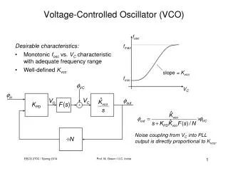
VCO Design. Z. Dilli, Mar 2012. VCO Design. Adapted from Ryan J. Kier, Low Power PLL Building Blocks , Ph.D. Dissertation, U. of Utah, 2010. System Design. VCO Source follower (external bias) Differential Amplifier (external bias) Inverter chain

E N D
VCO Design Z. Dilli, Mar 2012
VCO Design Adapted from Ryan J. Kier, Low Power PLL Building Blocks, Ph.D. Dissertation, U. of Utah, 2010.
System Design • VCO Source follower (external bias) Differential Amplifier (external bias) Inverter chain • Simulations show a center frequency of around 1 GHz, instead of 433 MHz as designed in the referenced dissertation • No varactor parasitics considered; bias voltage unknown • Around 4.3% tunability with certain assumptions about inductor parasitics • Varactor trade-off: Too small reduces tunability range; too large prevents oscillation
VCO-only Outputs Cvaractor varying from 160 fF (f=1.0737 GHz) to 450 fF(f=1.0385 GHz) Tuning range wider at lower bias currents (affects MOSFET capacitance)
VCO-only Outputs Ibias changing from <1 mA to >3 mA (by changing Vbias from 1 V to 3 V)
Source-follower and Self-biasing Differential Amplifier Two source followers for the differential outputs of the VCO, designed not to load the VCO output with excess capacitance Self-biasing DA increases output swing for the inverter chain operating more reliably Single-ended output taken out of DA
SF and SBDA operation Cvaractor=160 fF, f=1.0737 GHz
Inverter Chain Designed to drive a 1.5 pF load This is difficult with a full swing with this CMOS technology (0.6 um minimum width) at > 100s of MHz frequencies