Mutual Exclusion in Distributed Systems: Advanced Approaches
630 likes | 737 Views
Explore Raymond's, Suzuki-Kasami's, and Leader Election algorithms for mutual exclusion in distributed systems. Understand token-based and tree-based approaches, their advantages, and drawbacks.

Mutual Exclusion in Distributed Systems: Advanced Approaches
E N D
Presentation Transcript
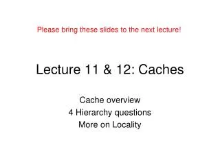
Lecture 11 and 12 Mutual Exclusion in distributed systems PART 3 SE-9048 Concurrency & Distributed System Huma Ayub (huma.ayub@uettaxila.edu.pk) Assistant Professor Software Engineering Department
Today’s Task • Last week we were discussing token ring structure • Today -----better approach • Raymond Tree Approach…… Suzuki-Kasami Algorithm broad cast Approach • Leader Election ….????
Token-based algorithms • LeLann’s token ring • Suzuki-Kasami’s broadcast • Raymond’s tree
Token-ring algorithm (Le Lann) • Processes are arranged in a logical ring • At start, process 0 is given a token • Token circulates around the ring in a fixed direction via point-to-point messages • When a process acquires the token, it has the right to enter the critical section • After exiting CS, it passes the token on • Evaluation: • N–1 messages required to enter CS • Not difficult to add new processes to ring • With unidirectional ring, mutual exclusion is fair, and no process starves • Difficult to detect when token is lost • Doesn’t guarantee “happened-before” order of entry into critical section
Ring Structure Problem • A problem with the ring structure approach is that the idle token is passed along the ring when no process is competing for it. • Raymond's Algorithm: Each process explicitly requests for a token and the token is moved only when if the process knows of a pending request.
Raymond’s AlgorithmTree Algorithm token based • Forms a directed tree (logical) with the token-holder as root • Initially Root: token holder. • Edges: directed towards root. • Every site has a variable holder that points to an immediate neighbor node, on the directed path towards root. (Root’s holder point to itself). • Each node has variable “Holder” that points to its parent on the path to the root. Root’s Holder variable points to itself • Each node i has a FIFO request queue Qi
Raymond’s Algorithm • Requesting CS • If Si does not hold token and request CS, sends REQUEST upwards provided its request_q is empty. It then adds its request to request_q. • Non-empty request_q -> REQUEST message for top entry in q (if not done before). • Site on path to root receiving REQUEST -> propagate it up, if its request_q is empty. Add request to request_q. • Root on receiving REQUEST -> send token to the site that forwarded the message. Set holder to that forwarding site. • Any Si receiving token -> delete top entry from request_q, send token to that site, set holder to point to it. If request_q is non-empty now, send REQUEST message to the holder site.
Raymond’s Algorithm … • Executing CS: getting token with the site at the top of request_q. Delete top of request_q, enter CS. • Releasing CS • If request_q is non-empty, delete top entry from q, send token to that site, set holder to that site. • If request_q is non-empty now, send REQUEST message to the holder site.
Raymond’s Algorithm: Example Token holder Step 1: S1 Token request S3 S2 S6 S7 S5 S4 Step 2: S1 S3 S2 Token S6 S7 S5 S4
Raymond’s Algm.: Example… Step 3: S1 S3 S2 S6 S7 S5 S4 Token holder
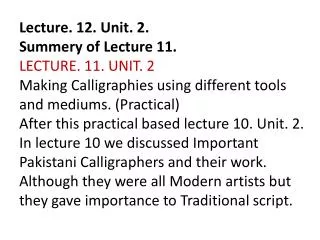
Raymond's Tree-Based Algorithm-- Example 1 1 2. node 2 receives the request, it sends the request to node 1 2 3 2 3 4 5 6 7 4 5 6 7 1. token is at node 1 node 5 made a request 3. node 4 also sends a request, node 2 receives it 1 1 2 3 2 3 4 5 6 7 4 5 6 7 4. token is at node 2 now node 2 becomes the root 5. node 5 gets the token, it enters CS 6. node 2 sends a request to node 5
Raymond's Tree-Based Algorithm-- Example 1 1 2 3 2 3 4 5 6 7 4 5 6 7 7. node 5 sends the token to node 2 8. node 4 gets the token, it enters CS 9. node 3 sends a request 1 1 2 3 2 3 4 5 6 7 4 5 6 7 10. the request from node 2 comes to node 4 11. node 3 gets the token, and becomes the root
Suzuki-Kasami’s Broadcast Algorithm • The site Broad Cast its request if it wants to enter its CS • The sites broadCast its request to all other sites if it does not have token and want to enter CS • If site receive a message when it is in CS, it gives token when it come out of CS. • Seems basic idea is so much simple
Suzuki-Kasami’s Broadcast Algorithm • The main design issues in this algorithm are: • (1) distinguishing outdated REQUEST messages from current ones, • (2) determining which site has an outstanding request for the CS.
Example req=[1,0,0,0,0] req=[1,0,0,0,0] last=[0,0,0,0,0] 1 0 2 req=[1,0,0,0,0] 4 req=[1,0,0,0,0] 3 req=[1,0,0,0,0] initial state
Example req=[1,1,1,0,0] req=[1,1,1,0,0] last=[0,0,0,0,0] 1 0 2 req=[1,1,1,0,0] 4 req=[1,1,1,0,0] 3 req=[1,1,1,0,0] 1 & 2 send requests
Example req=[1,1,1,0,0] req=[1,1,1,0,0] last=[1,0,0,0,0] Q=(1,2) 1 0 2 req=[1,1,1,0,0] 4 req=[1,1,1,0,0] 3 req=[1,1,1,0,0] 0 prepares to exit CS
Example req=[2,1,1,1,0] last=[1,0,0,0,0] Q=(2,0,3) req=[2,1,1,1,0] 1 0 2 req=[2,1,1,1,0] 4 req=[2,1,1,1,0] 3 req=[2,1,1,1,0] 0 and 3 send requests
Example req=[2,1,1,1,0] req=[2,1,1,1,0] 1 0 2 req=[2,1,1,1,0] last=[1,1,0,0,0] Q=(0,3) 4 req=[2,1,1,1,0] 3 req=[2,1,1,1,0] 1 sends token to 2
Performance • . Suzuki-Kasami’s algorithm requires 0 to N messages per CS invocation. • Synchronization delay in the algorithm is 0 or No message is needed and the synchronization delay is 0 if the site holds the token at the time of its request.
Divide the set of processes into subsets that satisfy the following two conditions: i Si i,j : i,j n-1 :: Si Sj ≠ Main idea. Each process i is required to receive permission from Si only. Multiple processes will never receive an OK. Maekawa’s algorithm S1 S0 0,1,2 1,3,5 2,4,5 S2
Maekawa’s algorithm Example. Let there be seven processes 0, 1, 2, 3, 4, 5, 6 S0 = {0, 1, 2} S1 = {1, 3, 5} S2 = {2, 4, 5} S3 = {0, 3, 4} S4 = {1, 4, 6} S5 = {0, 5, 6} S6 = {2, 3, 6}
Version 1 {Life of process I} 1. Send timestamped request to each process in Si. 2. Request received send ack to process with the lowest timestamp. Thereafter, "lock" (i.e. commit) yourself to that process, and keep others waiting. 3. Enter CS if you receive ack from each member in Si. 4. To exit CS, send release to every process in Si. 5. Release received unlock yourself. Then send ack to the next process with the lowest timestamp. S0 = {0, 1, 2} S1 = {1, 3, 5} S2 = {2, 4, 5} S3 = {0, 3, 4} S4 = {1, 4, 6} S5 = {0, 5, 6} S6 = {2, 3, 6} Maekawa’s algorithm
Proof of ME1. At most one process can enter its critical section at any time. Let i and j attempt to enter their Critical Sections Si Sj ≠ there is a process kSi Sj Process k will not send ack to both. So it will act as the arbitrator. S0 = {0, 1, 2} S1 = {1, 3, 5} S2 = {2, 4, 5} S3 = {0, 3, 4} S4 = {1, 4, 6} S5 = {0, 5, 6} S6 = {2, 3, 6} Maekawa’s algorithm
Possible Deadlock • Since processes do not communicate with all other processes in the system, CS requests may be granted out of timestamp order • example: • suppose there are processes Pi,Pj, andPk such that:Pj Ri and Pj Rk but Pk Ri and Pi Rk • Pi and Pk request CS such that tsk < tsi • if requestPi from reaches Pj first, then Pj sends reply to Pi and Pk has to wait forPi out of timestamp order • a wait-for cycle (hence a deadlock) may be formed
Proof of ME2. No deadlock Unfortunately deadlock is possible! From S0={0,1,2}, 0,2 send ack to 0, but 1 sends ack to 1; From S1={1,3,5}, 1,3 send ack to 1, but 5 sends ack to 2; Prom S2={2,4,5}, 4,5 send ack to 2, but 2 sends ack to 0; Now, 0 waits for 1, 1 waits for 2, and 2 waits for 0. So deadlock is possible! S0 = {0, 1, 2} S1 = {1, 3, 5} S2 = {2, 4, 5} S3 = {0, 3, 4} S4 = {1, 4, 6} S5 = {0, 5, 6} S6 = {2, 3, 6} Maekawa’s algorithm
Avoiding deadlock If processes could receive messages in increasing order of timestamp, then deadlock “could be” avoided. But this is too strong an assumption. So version 2 uses three more messages: - failed - inquire - relinquish S0 = {0, 1, 2} S1 = {1, 3, 5} S2 = {2, 4, 5} S3 = {0, 3, 4} S4 = {1, 4, 6} S5 = {0, 5, 6} S6 = {2, 3, 6} Maekawa’s algorithm-Version 2
What is new in version 2? Send ack and set lock as usual. If lock is set and a request with larger timestamp arrives, send failed (you have no chance). If the incoming request has a lower timestamp, then send inquire (are you in CS?) to the locked process. Receive inquire and at least one failed message send relinquish. The recipient resets the lock. S0 = {0, 1, 2} S1 = {1, 3, 5} S2 = {2, 4, 5} S3 = {0, 3, 4} S4 = {1, 4, 6} S5 = {0, 5, 6} S6 = {2, 3, 6} Maekawa’s algorithm-Version 2
Current Research: • 1) Hybrid Distributed Mutual Exclusion[4] A hybrid approach to Distributedmutualexclusion in which two algorithms are combined such that one minimizes message traffic and the other minimizes time delay. In a hybrid approach, sites are divided into groups, and two different algorithms are used to resolve local (intra-group) and global (inter-group) conflicts. EX: Develop a hybrid distributed mutual exclusion algorithm which uses Singhal's dynamic information structure algorithm [15] as the local algorithm to minimize time delay and Maekawa's algorithm [7] as the global algorithm to minimize message traffic.
Outline • Election algorithms – introduction • Traditional election algorithms • Bully algorithm • Ring algorithm • Wireless election algorithms
Need for a Coordinator • Many algorithms used in distributed systems require a coordinator • For example, see the centralized mutual exclusion algorithm. • In general, all processes in the distributed system are equally suitable for the role • Election algorithms are designed to choose a coordinator.
Election Algorithms • Any process can serve as coordinator • Any process can “call an election” (initiate the algorithm to choose a new coordinator). • There is no harm (other than extra message traffic) in having multiple concurrent elections. • Elections may be needed when the system is initialized, or if the coordinator crashes or retires.
ELECTIONS • There are at least two basic strategies by which a distributed system can adjust to failures. • operate continuously as failures occur and are repaired • The second alternative is to temporarily halt normal operation and to take some time out to reorganize the system. • The reorganization of the system is managed by a single node called the coordinator. • So as a first step in any reorganization, the operating or active nodes must elect a coordinator.
ELECTION AND SYNCHRONIZATION • Similar • Like Synchronization, all processors must come to an agreement about who enters the critical region (i.e. who is the leader) • Different • The election protocol must properly deal with the case of a coordinator failing. On the other hand, mutual exclusion algorithms assume that the process in the critical region (i.e., the coordinator) will not fail. • A new coordinator must inform all active nodes that it is the coordinator. In a mutual exclusion algorithm, the nodes not in the critical region have no need to know what node is in the region.
ELECTION ALGORITHMS • The two classical election algorithms by Garcia-Molina • Bully Algorithm • Invitation Algorithm • Ring Algorithm
The Bully Algorithm • State Information For Election • Status • Down,Election,Reorganization,Normal • Co-ordinator • The Current co-ordinator of the node • Definition • The State Information of the task being performed - the application algorithms, list of the participating nodes
Assumptions • Every process/site has a unique ID; e.g. • the network address • a process number • Every process in the system should know the values in the set of ID numbers, although not which processors are up or down. • The process with the highest ID number will be the new coordinator.
Requirements • When the election algorithm terminates a single process has been selected and every process knows its identity. • Formalize: every process pi has a variable ei to hold the coordinator’s process number. • ∀i, ei = undefined or ei = P, where P is the non-crashed process with highest id • All processes (that have not crashed) eventually set ei = P.
The Bully Algorithm - Overview • Process p calls an election when it notices that the coordinator is no longer responding. • High-numbered processes “bully” low-numbered processes out of the election, until only one process remains. • When a crashed process reboots, it holds an election. If it is now the highest-numbered live process, it will win.
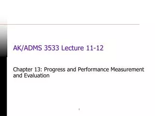
Figure 6-20 1 1 5 5 2 2 election OK 6 6 4 election 4 OK election 3 3 0 0 7 7 Process p sends an election message to all higher-numbered processes in the system.If no process responds, then p becomes the coordinator.If a higher-level process (q) responds, it sends p a message that terminates p’s role in the algorithm
The process q now calls an election (if it has not already done so). Repeat until no higher-level process responds. The last process to call an election “wins” the election. The winner sends a message to other processes announcing itself as the new coordinator. 1 5 2 election 6 4 election election 3 0 7 1 Figure 6-20 1 5 2 5 OK 2 6 4 6 coordinator 4 3 0 3 0 7 7 If 7 comes back on line, it will call an election
1 1 1 5 5 5 2 2 2 election election OK 6 6 6 4 4 election 4 OK election election election 3 3 3 0 0 0 7 7 7 1 1 5 2 5 OK 2 6 4 6 coordinator 4 3 0 3 0 7 7 Figure 6-20
Analysis • Works best if communication in the system has bounded latency so processes can determine that a process has failed by knowing the upper bound (UB) on message transmission time (T) and message processing time (M). • UB = 2 * T + M • However, if a process calls an election when the coordinator is still active, the coordinator will win the election.
A Ring Algorithm - Overview • The ring algorithm assumes that the processes are arranged in a logical ring and each process is knows the order of the ring of processes. • Processes are able to “skip” faulty systems: instead of sending to process j, send to j + 1. • Faulty systems are those that don’t respond in a fixed amount of time.
Election in a Ring • Process priority is obtained by organizing processes into a (logical) ring. Process with the highest priority should be elected as coordinator. • Each process has a successor • Initiation: • A process sends an ELECTION message to its successor (or next alive process) with its ID • Each process adds its own ID and forwards the ELECTION message • Leader Election: • Message comes back to initiator • Initiator announces the winner by sending another message around the ring