Download
1 / 13
130 likes | 238 Views
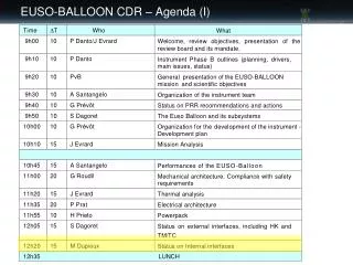
EUSO-BALLOON CDR – Agenda (I). EUSO-BALLOON DESIGN REVIEW, 18.12.2012, CNES TOULOUSE. Internal Interfaces. Michel DUPIEUX IRAP, Toulouse. Internal interfaces overview Batteries and Low Voltage power Supplies PDM interfaces DP interfaces HK Interfaces List of cables Status.

E N D
EUSO-BALLOON DESIGN REVIEW, 18.12.2012, CNES TOULOUSE Internal Interfaces Michel DUPIEUX IRAP, Toulouse • Internal interfaces overview • Batteries and Low Voltage power Supplies • PDM interfaces • DP interfaces • HK Interfaces • List of cables • Status
Internal interfaces overview DP PDM EC-Front GPSR IR-CAM EC-DYNODE CLKB LVPS1-DP EXT MAPMT EC-HV CCB EC-ANODE SIREN SPACEWIRE /PCI CNES Telemetry CPU EC-ASIC LVPS2-DP DST Batteries PDM-B Bat Controller LVPS-PDM HVPS-2 PWP HK HVPS-1 LVPS-HK Sensors Motors EC-Back TLS Internal Interfaces – Michel Dupieux
Power pack interfaces Interfaces Connectors Power Pack & Main Fuses Main switch Connectors Individual fuses - CNES Provide the batteries - IRAP purchases the components and does the Assembly and tests the Power Pack Internal Interfaces – Michel Dupieux
Low Voltage Power Supplies Overview DP PDM EC-Front GPSR IR-CAM EC-DYNODE CLKB LVPS1-DP EXT MAPMT EC-HV CCB EC-ANODE SIREN SPACEWIRE /PCI CNES Telemetry CPU EC-ASIC LVPS2-DP DST Batteries PDM-B Bat Controller LVPS-PDM HVPS-2 PWP HK HVPS-1 LVPS-HK Sensors Motors EC-Back TLS Internal Interfaces – Michel Dupieux
PDM interfaces • Interfaces with: • CCB µSubd51 • HVPS µSubd9 • HK µSubd9 • POWER Subd9 120 pins ASIC A ASIC B ASIC C ASIC D ASIC E ASIC F Fixation screw EC_HV Kapton cable A B C D E F 68 pins 68 pins 68 pins 68 pins 68 pins 68 pins MAPMT Internal Interfaces – Michel Dupieux
Data processor Block Diagram DP LVPSs DP LVPSs 28V DP LVPSs TLS PWP DP LVPS V, A Monitor v HK system HL-CMD CC SIREN system RS 422 adaptor Analog ( T) RS 232 12V RS422 CPU 5V Analog ( T) CCB Ethernet v SpaceWire to PCI SpaceWire 5V v Data Storage v SATA CLKs, Sync, Trig, Busy 5V CLK board v v PCI SpaceWire CMD SPI Fast parallel link V, T mon. SPI v RS232 1PPS 5V GPS 5V Visible cam (adv. opt.) PDM box IR Camera (adv. opt.) Internal Interfaces – Michel Dupieux
Description of the DP and its components Internal Interfaces – Michel Dupieux • The DP functionality is obtained by connecting different specialized items, which form a complex system. • The main subassembly items are: • Control Cluster Board (CCB) • Main processing unit (CPU) • Data Storage (DST) • Housekeeping system (HK) • Clock Board (CLKB) • GPS receiver (GPSR) • Data Processor Power Supplies (DP-LVPS1-2-3) • PDM Power Supply (PDM-LVPS)
Description of the DP and its interfaces CPU LVPS HK HK CCB LVPS PDM LVPS1 CLK GPS LVPS2 DP box modules Internal Interfaces – Michel Dupieux
HK interfaces Internal Interfaces – Michel Dupieux
HK Boards and interfaces Individual boards’functionality: PCB 05: LENSES, LVPS-PDM, LVPS-HK: (DC25-DB25). PCB 04: LVPS1-DP, LVPS2-DP: (DC37-DB25). PCB 03: SIREN-HK, CPU-HK, PDM-HK (DE9-DE9-DA15). PCB 02: CCB-HK, CLKB-HK: (DB25-DB25). PCB 01: POWER-HK, GPS-HK, HVPS-HK: (DE9-DA15-DA15). Internal Interfaces – Michel Dupieux
Complete list of cables Internal Interfaces – Michel Dupieux
Status on Internal & External Interfaces • Internal Interfaces • All the interfaces have been checked with the sub-system responsibles. • A list of the key points verification is done below: • All interfaces were checked • All connectors pinout were checked • Each Pin on each connector was checked • Each Sub-system have its own cables and connectors lists. • All the cables on both side were checked • Connectors and cables have single reference • One responsible for each cable is done • Maximum Use of Female connector on Front panel • Use Female connectors on power side. • External Interfaces • On the external interfaces the same work has been done Internal Interfaces – Michel Dupieux