Download
1 / 31
390 likes | 846 Views
Basics of IC design. Miroslav Havránek. Integrated circuit. Electronic device. PCB. Integrated circuit. Transistor. Integrated circuit - core. Interconnection. IC design in HEP. Experiment ATLAS. Large Hadron Collider. ~ 100 000 000 read-out channels ~ 1 000 000 000 collisions

E N D
Basics of IC design Miroslav Havránek
Integrated circuit Electronic device PCB Integrated circuit Transistor Integrated circuit - core Interconnection
IC design in HEP Experiment ATLAS Large Hadron Collider ~ 100 000 000 read-out channels ~ 1 000 000 000 collisions every second ~ 6.4 M strips ~ 80 M pixels Requirements for FE electronics: • Radiation hard • Low power • High speed • Low mass electronics • Long term reliability Hard to meet with commercial electronics !!!
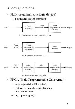
Why doing IC design? A pplication S pecific I tegrated C ircuit • IC Design • = maximum freedom of adjusting parameters of the • electronic circuit to meet the specification • = freedom of technology choice Bipolar technology CMOS technology • High speed – low noise applications • High power consumption • Low density integration • Typical applications: TTL logic, OpAmps, discrete components • Widely used in the past • Large integration density • Scaling • Low power • Low cost • Most of modern electronics is fabricated • by CMOS
CMOS technology • CMOS technology uses MOSFET transistors • of both types: NMOS, PMOS • Bipolar transistor only parasitic (poor parameters) • Low cost (in large scale production) • High integration density • Scaling • - smaller transistors • - higher complexity • - higher power density 14 nm 1947 2006 2011 2013 ?
Silicon foundry • IC fabrication requires clean environment • -> clean rooms • Ordinary room 500.000 – 1.000.000 in m3 • Clean room in silicon foundry • ~100 particles in m3
Electronic components in CMOS technology • Active components • - MOSFET transistors • - parasitic bipolar transistors (poor parameters) • CMOS technology is optimized for fabrication of NMOS and PMOS transistors, • passive components have limited performance (precision, linearity) • Passive components • - resistors • - capacitors • - inductors (used in RF application) • - diodes • Hard to integrate large capacitors (> 10 pF) and large resistors (> 50 kΩ)
Anatomy of MOSFET Transistor Polysilicon gate Drain contact Source contact P-well contact Gate oxide SiO2 (thickness ~ several nm) Channel High purity Monocrystalline silicon substrate <100> (epi-layer)
Inversion layer and threshold voltage • Vgs = 0 N+ P-WELL junction – depleted region by diffusion • Vgs > 0 (but small) -> depletion of bulk under gate, accumulation of minority charge carriers • Vgs > (100s mV) concentration of electrons is equal to concentration of holes • Vgs = Vt ….. Vt is threshold voltage • Vgs > Vt– inversion layer (conductive channel) • if Vds > 0 current between drain and source
NMOS and PMOS transistors MOSFET is 4-terminal device D NMOS G B S S PMOS G B D
NMOS transistor - a closer look Saturation region Linear region • VGS > VT, VDS < VGS - VT • - transistor operates in linear region • - transistor behaves as a resistor • VGS > VT, VDS > VGS – VT • - transistor operates in saturation • - transistor behaves as a current source
NMOS transistor - closer look Weak inversion region • VGS < VT • - sub-threshold region • - drain current depends exponentially on VGS • - low power applications Transconductance Output conductance Transconductance can be adjusted by changing aspect ratio of transistor dimensions λ … channel length modulation parameter short channel transistors have large λ
Resistors in CMOS technology Metallic resistor - ρsq ~ 100 mΩ/sq w l N-well resistor - ρsq ~ 1 kΩ/sq - non-linear, not shielded from substrate Diffusion resistor - ρsq ~ 10 Ω/sq - non-linear, shielded from substrate • Polysilicon resistor • - ρsq ~ 10 Ω/sq • - linear metal polysilicon
Capacitors in CMOS technology < 90 nm > 90 nm METAL 1 MOM – Metal Oxide Metal - parasitic capacitance between metals - small capacitance density ~ 50 aF/µm2 METAL 2 MIM – Metal Insulator Metal - parasitic capacitance between two metal layers separated by thin (~100nm)insulator layer - large capacitance density ~ 1fF / µm2 METAL Thin oxide layer MOSCAP - capacitance between gate and substrate - large capacitance density ~ 5-10 fF / µm2 - non-linear behavior
Fabrication of MOSFET transistors - photolitography 1. Deposition of silicon oxide and nitride 4. Removing illuminated photoresist, etching silicon nitride, etching isolation tranches in silicon 2. Photoresist deposition 5. Filling isolation trenches with SiO2 3. Illumination of the photoresist through the mask 6. Ion implantation (Phosphor ~100 keV) -> N-well formation
Photolitography 7. Ion implantation (Boron ~100 keV) -> P-well formation 10. Deposition of polysilicon 11. Photoresist deposition, illumination through mask 8. N-well and P-well are ready for implementing NMOS and PMOS transistors 9. Gate oxide deposition 12. Gates are formed
Photolitography 13. Low energy implantation of Boron dopants -> forming P+ regions of drain and source 16. Silicidation 16. BPSG deposition 14. Low energy implantation of Phosphor dopants -> forming N+ regions of drain and source 17. Etching, vias, deposition of METAL1, BPSG isolation 15. Removing photoresist and oxide from source and drain
Design Software • IC = Complex systems of many components and interconnections • => high level of automation is needed for • design and simulations • EDA – Electronic design automation • Design software : Cadence Virtuoso • - schematic editor • - simulation tools ADE… • - place and route tools (Encounter) • - layout editor • Process Design Kit: • Libraries with electronic components • Models of electronic components • Customization of design environment • Design rules • Process documentation
Analog vs Digital design Digital circuit Analog circuit
Analog design flow Schematic capture Specification Simulation Does it meet specs? NO NO YES Does it meet specs? Corners & MC simulation YES Layout Capture DRC/LVS NO OK? Does it meet specs? NO YES Post-layout simulation Tape-Out
Digital design flow HDL design Specification Behavioral simulation Does it meet specs? NO YES Synthesis Constraints Place and route DRC/LVS NO OK? Does it meet specs? YES NO YES Post-layout simulation Tape-Out
Design rules • IC – complex system of millions of transistors, interconnections, vias => all of them have to work!! • IC designer have to follow design rules provided by manufacturer and general rules of CMOS design General design rules Process specific design rules • - Folding of large transistors • Minimizing mismatch effects • Separation of analog and digital power lines • Provided by manufacturer • EDA allows DRC check to avoid design rule violation • 100s, in modern processes 1000s of design rules • Distances between metals, transistors, wells etc. Design for manufacturability Yield of IC production can be significantly improved by proper layout
General design rules • Thickness of gate oxide in modern CMOS technologies ~ several nm • MOSFET is ESD (Electrostatic discharge) • Typical operating voltage in deep submicron technologies < 2V • Typical ESD event ~ several kV from capacitance of ~ 100 pF • Transistors must be protected from high voltage from outside • => ESD protection is part of IO pads • Antenna effect • - long metal routes can accumulate • charge during processing changing metal layers using antenna diodes
General design rules • Use appropriate metal width for high current lines • - max current density ~ 1 mA / um width … usually we use much smaller current density • - don’t use single vias !! • Transistor folding • - transistors with large aspect ratio W/L are often • folded in many-finder layout • - layout is more compact • - drain and source area reduced -> CSB, CDB smaller • - gate resistance is smaller -> transistor is faster Common centroid design • Transistor mismatch Dummy transistors
Example design - invertor • Specification: • - design an invertor in 65 nm CMOS technology, VDD power supply = 1.2V • - switching frequency 500 MHz, load capacitance = 50 fF • - rise-time = fall-time < 100 ps • - power consumption < 45 µW W/L=200n/60nl W/L=200n/60nl
Test-bench and simulations CLOAD = 0 fF tRISE = 4.2 ps tFALL = 6.5 ps Power = 0.27 µW INPUT OUTPUT … but what if CLOAD = 50 fF ??
Test-bench and simulations CLOAD = 50 fF tRISE = 230 ps tFALL = 305 ps Power = 31.6 µW … transistors don’t provide enough driving current -> increase W/L INPUT OUTPUT CLOAD = 50 fF tRISE = 75 ps tFALL = 75 ps Pwr = 39 µW Meets specs !! INPUT W/L=3.5µ/60n W/L=1.6µ/60n OUTPUT
Process variations -> Monte Carlo simulations POWER tR tF
Layout N-WELL CONTACT PMOS INPUT NODE OUTPUT NODE NMOS P-WELL CONTACT 1.9 × 4.5 µm2