Download

1 / 39
400 likes | 732 Views
Introduction to IC Design. Tsung-Chu Huang ( 黃宗柱 ) Department of Electronic Eng. Chong Chou Institute of Tech. Email: tch@dragon.ccut.edu.tw 2003/11/03. Outline. CMOS Logic Gate Design Standard Cell Layout Gate Array Layout Sea of Gates CMOS Layout Guideline Transmission Gate Layout

E N D
Introduction to IC Design Tsung-Chu Huang (黃宗柱) Department of Electronic Eng. Chong Chou Institute of Tech. Email: tch@dragon.ccut.edu.tw 2003/11/03
Outline • CMOS Logic Gate Design • Standard Cell Layout • Gate Array Layout • Sea of Gates • CMOS Layout Guideline • Transmission Gate Layout • MUX Layout • CMOS Logic Structures • Clocking Strategies • I/O Structures • Low-Power Design
Fan-In and Fan-Out D Fanout=4 A A Fanin=3 D To that nearest to output in the serial transistors
CMOS Gate Stage-Ratio Principle (Review) IO PAD
Transistor Stage-Ratio Principle Rp/s ↓ 1 1 s:1 1 OCg rOCg 1 ↓ CDS CDS CDS output part internal part
Transistor Stage-Ratio Principle Equal Rise/Fall Time Design Normalized-mobility
Transistor Stage-Ratio Principle High-Speed Design Guideline • Use NAND instead of NOR gates • Place inverters at high-fanout nodes • Fanin < 5; Fanout < 10 • Use min.-sized gates on high-fanout nodes; • Keep Rise/Fall edges sharp
Complex Logic Gate Layout Euler Path (Review)
CMOS(互補金氧半) Logic P型網路 F X N型網路 • P型網路為F(X)的Relay logic • N型網路為F(X)的Relay logic AND與OR互換即可
Stick Diagram 2/0.35 1/0.35 • 常用佈局表示法及簡化佈局法 • 格子(Grid)狀文字(Font)表示法 • EDIF 為一種(層次,對角座標)的表示法 • Stick diagram: 草圖用,將不重要寬度省略 • 例:
例如:F=(A+B)(C+D) 因為F=(A+B)(C+D) A C B D A B A B D C A B C D 因為F= A B + C D C D P型網路為: N型網路為:
尤拉路徑 (Euler Path) • 拓樸學證明各輸入開關X與X交叉通過! F D A B F S • 十八世紀拓樸學被用來簡化CMOS邏輯閘佈局 • N型路徑為N型Relay-logic網路 • P型路徑為P型Relay-logic網路
尤拉路徑 (Euler Path)佈局法 F D A B F S A B VDD 再畫出兩倍寬度的P+IMP D A B F 先畫出一倍寬度的N+IMP S A F B S VSS
Interlaces of Diffusion Lines Vdd A B C D E A A B E D C B E Vss Out D C A B E D C Out
Minimum Interlace Algorithm A Out B F C Vdd E Out Out D D C E F A B Vss Example:
Minimum Interlace Algorithm A B C 2 interlaces D E F • Adding a pseudo input to each sub-gate such that each sub-gate has odd inputs.
Minimum Interlace Algorithm A B C D F E • Rotate each axis to reduce the inner interlaces
Output Capacitance Minimization COA Put Output-point here because A COBCD >> COA B C D COBCD
Stacking along Diffusion Lines Example: considering a buffer with a stage ratio of 2 1:2 Area: A1 Area: A2 Wn1+Wn2 Ln1+Ln2 Area: A3 Vinv↗
Channel Routing I H A B B C C A D F D To reduce #Tracks E G I B A G F H E
LEA: Left-Edge Algorithm Edge Length B D C A E G F • Sort by length • Select from Left Edge
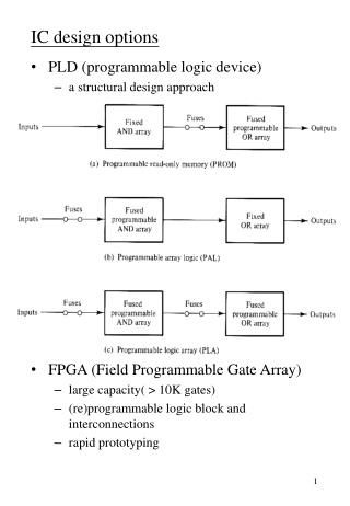
Rapid Prototyping • Prototyping: Q<<Qproduct for test, debug, verification. • Rapid Prototyping: t(Q) << t(Qproduct) • Usual Rapid Prototyping wrt. Full Custom • Semi-Custom: saving the prior processes • Weinberger Array, Gate Array, SOG, e.t.c. • Standard-Cell: saving • PLD • SPLD • CPLD • FPGA
Weinberger Array (NOR Logic) A B C D E F G
Physical Layout Skills • Widening methods: • Crossover:
Physical Layout Skills • Dog-bone/Dog-Leg: No need to change layers for crossing • More usage of white space: Rubber forcing
Folding Lines of Diffusion Example: Full Adder
Folding Lines of Diffusion Example: Full Adder A B C Co A B C Co Sum
Folding Lines of Diffusion Example: Sum=A⊕B⊕C F Y V F Y F Y Y F V S X S X F S X S F X A A B B B A C C
Connections of Standard Cells 1. Butting 1. Wired 3. Feedthrough
Multiplex A B A C A Z 0 C B 1 B C
Multiplex Layout A B
Pass-Transistor and Transmission Gate A PASS Transistor Logic Circuit Pull-up or Pull-down High-Z B or Vth-Degrade PASS Transistor Logic Circuit
4-Transistor XOR and XNOR A B A Bui et al. New 4-Transistor XOR and XNOR Designs, AP-ASIC2000.
Scope & Review on the Midterm • Lectures from 9/22~11/3. • Stick diagram, inv(ENM, ERF, Stage) • Multiple choice on common guidelines • SPICE Netlist and 3 Major Analyses