Introduction to Computer Organization: Processor Design and Datapath Architecture Overview
This material covers essential concepts of computer organization and processor design, focusing on datapath architecture. It explores ALU construction, modular design, and the parallel execution of operations. Key topics include the implementation of MIPS ISA, memory systems, control mechanisms, and clocking methodologies. The outline addresses data manipulation, decision-making processes, and the design challenges in building a functional processor. It serves as a robust guide for understanding CPU performance, architecture, and the principles of digital design.

Introduction to Computer Organization: Processor Design and Datapath Architecture Overview
E N D
Presentation Transcript
CDA 3101 Fall 2013Introduction to Computer Organization Processor Organization Datapath Design 4 October 2013
Review • Construction of the ALU • Building blocks (digital design gates) • Modular design • Multiplexor chooses operation • All operations are performed in parallel • Carry lookahead adder • Computer arithmetic • Finite precision • Laws of algebra do not always hold • Integers: two’s complement representation • Floating point: IEEE 754 standard
Overview • Computer organization (microarchitecture) • Processor organization • Datapath • Control • Register file • Processor implementation overview • Clocking methodologies • Sequential circuits • Latches • Registers
Processor Performance CPU time =IC* CPI *Cycle time Program Compiler ISA Microarchitecture Hardware
Computer Organization Address Bus Memory Subsystem Data Bus Processor Control Bus I/O device I/O device . . . I/O Subsystem
The Processor • Processor (CPU) • Active part of the computer • Does all the work • Data manipulation • Decision-making • Datapath • Hardware that perform all required operations • ALU + registers + internal buses • The brawn • Control • Hardware which tells the datapath what needs to be done • The brain
Processor Organization Address bus Data bus Control bus signals Control signals Control Unit Data values Registers Control signals Data values (operands) ALU Data values (results)
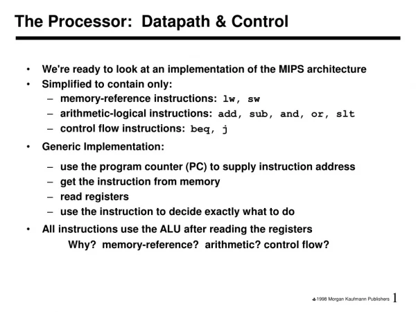
Implementation of MIPS • ISA determines many aspects of implementation • Implementation strategies affect clock rate and CPI • MIPS subset to illustrate implementation • Memory-reference instructions • Load word (lw) • Save word (sw) • Integer arithmetic and logical instructions • add, sub, and, or, and slt • Branch instructions • Branch if equal (beq) • Jump (j)
Implementation Overview Data Instruction memory rd Data memory rs Address Registers PC ALU Address rt Instruction +4 Data imm Opcode, funct Controller • Datapath is based on register transfers required to execute instructions • Control causes the right transfers to happen
Logic and Clocking • Combinational elements • Outputs depend only on current inputs • Example: ALU (adders, multiplexers, shifters) • Sequential elements • Contain state • Output depend on input and state • Inputs: data values and clock • Memory, registers • Asserted signal: logically high
Clocking Methodology • Determines the order of (gate) events • Defines when signals can be read/written • Clock: circuit that emits a series of pulses clock cycle time Timing diagrams clock Asymmetric clock C (C1 AND C2) Rising edge Falling edge
Edge-Triggered Clocking • Either the rising edge or the falling edge is active • State changes only on the active clock edge State element 1 State element 2 Combinational logic clock State element Combinational logic
NOR SR Latch State 0 State 1 S - set Inputs Outputs: Q and Q R - reset
Clocked D Latch D C Q Output is initially deasserted
D flip-flop D D Q D Q Q D latch D latch Q C C Q C Setup time D hold time C Q Falling-edge trigger, output is initially deasserted
Register File Read ports Write port
Core Topic –Datapath Design • Datapath implements fetch-decode-execute • Design Methodology Determine instruction classes and formats Build datapath sections for each instr.fmt. Compose sections to yield MIPS datapath • Challenge #1: What are instruction classes? • Challenge #2: What components are useful?
Simple Datapath Components PC Read Addr Instruction Instruction Memory • Memory stores the instruction • PC address of current instruction • ALU executes current instruction Increment program counter + 4 fetch
R-format Datapath ALU op Register File 3 Read Reg 1 Read Reg 2 Write Register Write Data Read Data 1 Read Data 2 Instruction ALU Register Write • Format:opcode r1, r2, r3 Zero Result
Load/Store Datapath Issues • lw $t1, offset($t2) • Memory at base $t2 with offset • lw: Read memory, write into register $t1 • sw: Read from register $t, write to memory • Address computation – ISA says: • Sign-extend 16-bit offset to 32-bit signed value • Hardware: Data memory for read/write
Load/Store Datapath Components 16 32 Sign Extend MemWrite Address Read data Write data Data Memory 1101 … 0011 1111 1111 1111 11111101 … 0011 MemRead
Load/Store Datapath Actions • Register AccessRegister File --Instruction/Data/Address Fetch • Memory Address CalculationALU -- Address Decode • Read/Write from MemoryData Memory • Write into Register FileRegister File -- Load/Store Instruction Execute
Load/Store Datapath Fetch DecodeExecute
Branch Datapath Issues • beq $t1, $t2, offset • Two registers ($t1, $t2) compared for equality • 16-bit offset to compute branch target address • Branch target address – ISA says: • Add sign-extended offset to PC • Base address is instruction after branch (PC+4) • Shift offset left 2 bits => word offset • Jump to target • Replace lower 26 bits of PC with lower 26 bits of instruction shifted left 2 bits
Branch Datapath Actions • Register AccessRegister File --Instruction/Data Fetch • Evaluate Branch ConditionALU #1 • Calculate Branch TargetALU #2 --Branch Computation – similar to Decode • Jump to Branch TargetControl Logic -- Branch Instruction Execute
Branch Datapath Fetch DecodeExecute
Delayed Branch (MIPS) • MIPS ISA: Branches always delayed • Instr. Ib following branch is always executed • condition = false => Normal branch • condition = true => Ib executed Why bother? • Improves efficiency of pipelining • Branch not taken (false condition) can be common case
Conclusions • MIPS ISA: Three instruction formats (R,I,J) • Datapath designed for each instruction format • Datapath Components: -- R-format:ALU, Register File -- I-format:Sign Extender, Data Memory -- J-format:ALU #2 for target address comp’n. Trick: Delayed branch to make pipeline efficient Think: Weekend !