Download
1 / 37
390 likes | 628 Views
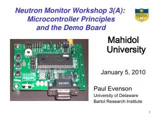
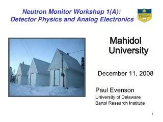
Neutron Monitor Workshop 1(A): Detector Physics and Analog Electronics. Mahidol University December 11, 2008 Paul Evenson University of Delaware Bartol Research Institute. Workshop Series Idea. Introduce students to technical aspects of neutron monitor operation

E N D
Neutron Monitor Workshop 1(A): Detector Physics and Analog Electronics Mahidol University December 11, 2008 Paul Evenson University of Delaware Bartol Research Institute
Workshop Series Idea • Introduce students to technical aspects of neutron monitor operation • Rotating workshop series that will repeat every two years at a two per year rate • Independent enough so students can join at any point • Accommodate wide skill range with an emphasis on “hands on” experience and individual discussion
Workshop Series Plan • Detector operation • Detector Physics and Analog Electronics • Art and Science of Soldering • Digital Circuits (including theory of the peripheral devices like the barometers). • Microcontrollers (including data transfer methods within the electronics system) • Real time data acquisition • Principles of Telemetry and Data Acquisition • Data Conversion and Manipulation with Visual Basic
Neutron Monitors • High energy cosmic rays are rare. Observing them at high time resolution requires a large detector. • Ground based instruments remain the state-of-the-art method for studying these elusive particles. • Neutron monitors on the surface record the byproducts of nuclear interactions of high energy primary cosmic rays with Earth's atmosphere.
Neutron Monitor Principle • An incoming hadron interacts with a nucleus of lead to produce several low energy neutrons. • These neutrons thermalize in polyethylene or other material containing a lot of hydrogen. • Thermal neutrons cause fission reaction in a 10B (7Li + 4He) or 3He (3H + p) gas proportional counter. • The large amount of energy released in the fission process dominates that of all penetrating charged particles. There is essentially no background.
Simulated Interaction In a Neutron Monitor http://www.bartol.udel.edu/~clem/nm/display/intro.html
BP-28 Neutron Detector • Stainless steel cylinder 1.90 m long and 15 cm diameter • Filled to 20 cmHg with 96% enriched 10BF3 • 0.2 mm diameter anode wire • Capacitance is about 20 pF
BP-28 Neutron Detector n • 10Boron has a huge cross section for neutron absorption • It then splits into 7Li and 4He (an alpha particle) • Unlike 235U you cannot make a bomb out of it because no secondary neutrons are produced He Li
BP-28 Neutron Detector • About 94% of the reactions leave the 7Li in an excited state, releasing 2.30 MeV of kinetic energy • About 6% go directly to the ground state, releasing 2.78 MeV • This can produce about 2x10⁵ free electrons • Most of the kinetic energy appears in the alpha particle • The alpha particle can hit the wall of the detector and not deposit all of its energy
BP-28 Neutron Detector • The cathode is maintained at about negative 2.8 kilovolts • The anode is near ground • Electrons drift toward the anode in the resulting electric field • Using V=Q/C this would produce a signal of about 1.5 millivolts
BP-28 Neutron Detector • Actually the signal is amplified somewhat in the strong electric field very near the wire • Electrons ionize the gas, producing a cascade • For appropriate potentials, the amplification is proportional • The gain is approximately 20 for the tube in the micromonitor
BP-28 Tubes Degrade With Age • Spectra taken annually from one of the neutron detectors used at South Pole are shown from the installation of the detector in 1997 (thick black curve) to 2003 (thick red curve) • The curves are normalized so that all have equal area. • Each ionization cascade dissociates some of the BF3 and material “plates out” non uniformly on the anode wire, increasing its effective diameter • Larger diameter lower field and less amplification
BP-28 Tubes Degrade With Age • The South Pole monitor had a very high count rate so the process there is rapid • Despite the broadening of the resolution, the average pulse height has only been reduced by 13% over this interval (vertical lines). • Because few events have pulse heights near the counting discriminator (arrow), the tube degradation has a negligible impact on count rate. • This tube should still have a long useful life at the lower count rates on Doi Inthanon, where it now lives
Signal Examples • The primary signals (orange) are all different because the path of the alpha particle is randomly oriented • If the path is parallel to the wire, nearly all the charge arrives at once • If it is perpendicular to the wire there is a spread of arrival times • Our problem is to process these signals so they become uniform (green then blue) • Then we can produce reliable digital signals ( red) to count the interactions • Now we discuss how to do this
Operational Amplifiers • To understand electronic circuits fully, it is still necessary to know how resistors, capacitors, transistors, etc., work • For many purposes, however, the basic building block today is the integrated “operational amplifier” • The following discussion is mostly extracted from the Wikipedia article
Basic Non-inverting Amplifier Circuit • Key Concepts: • Because the gain is “infinite” it does not matter what the gain is • Properties of the circuit are determined by external components
What We Really Need … • We really don’t want simply to amplify the voltage on the wire, we want to integrate the charge as it accumulates • This can be done by including capacitors as feedback elements to produce a charge sensitive amplifier • The following is from a Hamamatsu document
Charge Sensitive Amplifier Principle of Operation • The key concept here is that of a virtual ground • All of the charge is drained from the wire • The total charge extracted is integrated and held by Cf
Shaping Stage • This type of waveform is still not optimal (I will tell you why later) so typically a shaping stage is added • Here is a discussion of the very nice but very expensive Amptek 203 • We would have used these except they cost $600 each -- about what the whole remote board costs the way we eventually did it
Why These Outputs are Nice • Height of the pulse is proportional to the total charge on the wire • Uniform shape with a flat top is easier to measure • Bipolar output has no “DC” component • Now we need to • Count pulses above a prescribed threshold • Accumulate spectra for diagnosis
Discriminator • Computers and logic are simpler if the analog signals are converted to digital signals • The simplest conversion device is the discriminator, which produces an output signal each time the input exceeds a specified threshold
R R - + The Simplest Discriminator is Just an Operational Amplifier • The threshold is set by the voltage applied to the negative input • When the positive input exceeds this level the output (because of the high gain) goes from zero to full scale • This is crude but often effective
R 2 R 3 R 1 R 4 - + - + By Adding a Little Positive Feedback You Make a “Schmidt Trigger “ • This type of trigger has hysteresis – it will not “chatter” with near threshold pulses • It is also available pre-packaged • We still need to add circuits that make the discriminator output have a length independent of the input amplitude – typically called “one shots”
Signal Amplitude Measurement • The next simplest thing to do is to measure the amplitude of a signal • In our case we need to measure the amplitude only once, because the shaping circuit has made the peak voltage of the pulse proportional to the charge • We start this with a circuit called a “peak detector” which remembers the maximum amplitude of the pulse
D C Peak Detector • The model for a peak detector is just a diode and a capacitor • The peak detector holds the signal until it can be “digitized” • Actual circuits use comparators to eliminate the “diode drop” • They also include provisions for gating the circuit and discharging the capacitor when the measurement is complete
2 1 4 R - + ADC (Analog to Digital Converter) From Peak Detector • The “DC” level produced by the peak detector is then measured with an ADC, whichis primarily a digital device • Logic circuitry generates a voltage output by switching fixed, constant currents onto a fixed resistor • (You can visualize a constant source as a very large resistor connected to a very high voltage, but the real circuit is more clever than that) • The logic uses our old friend the differential amplifier as a comparator to determine when it has generated a voltage equal to that on the output of the peak detector • Details of how logic can “hunts” for the proper voltage will be discussed in some more detail in Workshop 3
Actual Circuits in the “Remote” • Now I briefly go through the implementation of these concepts in the “micromonitor” • Alex will then set up a couple of demonstrations of the signals that I have already discussed • Those who are interested in more details are welcome to stay and ask questions
Charge Amp and Shaper • Our circuit has two stages, but due to our decision to use cheap components neither has the pure function of the Amptek system. • The cost is about $3.00 vs $600.00 • For an 18 tube monitor it adds up
Counting Discriminator • The shaped pulse is compared with a standard level • A “one shot” is used to limit the pulse length to 3 microseconds • Note that the hysteresis circuit “kicks back” when the discriminator “fires”
Peak Detector • The PHA discriminator is set lower than the counting discriminator • When it fires the gate (yellow) opens for enough time to enclose any possible true peak • This (cheap) peak detector (green) is not fast enough to follow the signal, and holds it slightly after the real peak • The clear and reset come much later, when the microcontroller (Workshop 3) has used other circuitry (Workshop 2) to measure the amplitude of the signal • Note that the counting circuitry is independent of this, and can count at a much higher rate than that at which PHA may be taken
ADC • The ADC we use has only a few external components • It is operated by the microcontroller • Note that the ADC has several inputs that can be selected • In addition to measuring the pulse height spectrum the ADC is used to monitor various internal volatages