Download
1 / 35
350 likes | 449 Views
Learn about BJT physics, Ebers-Moll equations, charge storage mechanisms, construction, layout, and operation principles. Understand small-signal models, current characteristics, and device optimization strategies.

E N D
Lecture 14:Bipolar Junction Transistors Prof. Niknejad
Lecture Outline • Diode Small Signal Model • Diode Charge Storage (6.4.4) • Diode Circuits • The BJT (7.1) • BJT Physics (7.2) • BJT Ebers-Moll Equations (7.3) • BJT Small-Signal Model University of California, Berkeley
Diode Small Signal Model • The I-V relation of a diode can be linearized University of California, Berkeley
Diode Capacitance • We have already seen that a reverse biased diode acts like a capacitor since the depletion region grows and shrinks in response to the applied field. the capacitance in forward bias is given by • But another charge storage mechanism comes into play in forward bias • Minority carriers injected into p and n regions “stay” in each region for a while • On average additional charge is stored in diode University of California, Berkeley
Charge Storage • Increasing forward bias increases minority charge density • By charge neutrality, the source voltage must supply equal and opposite charge • A detailed analysis yields: Extra charge Stored in diode Time to cross junction (or minority carrier lifetime) University of California, Berkeley
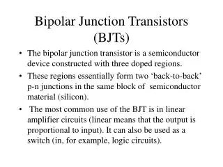
Emitter (P) Collector (N) Base (P) Base (N) Collector (P) Emitter (N) Ideal BJT Structure • NPN or PNP sandwich (Two back-to-back diodes) • How does current flow? Base is very thin. • A good BJT satisfies the following University of California, Berkeley
Actual BJT Cross Section • Vertical npn sandwich (pnp is usually a lateral structure) • n+ buried layout is a low resistance contact to collector • Base width determined by vertical distance between emitter diffusion and base diffusion University of California, Berkeley
BJT Layout • Emitter area most important layout parameter • Multi-finger device also possible for reduced base resistance University of California, Berkeley
BJT Schematic Symbol • Collector current is control by base current linearly • Collector is controlled by base-emitter voltage exponentially University of California, Berkeley
BJT Collector Characteristic • Ground emitter • Fix VCE • Drive base with fixed current IB • Measure the collector current University of California, Berkeley
Collector Characteristics (IB) Saturation Region (Low Output Resistance) Breakdown Linear Increase Reverse Active (Crappy Transistor) Forward Active Region (Very High Output Resistance) University of California, Berkeley
Base-Emitter Voltage Control Saturation Region (Low Output Resistance) ~0.3V Breakdown Exponential Increase Reverse Active (Crappy Transistor) Forward Active Region (High Output Resistance) University of California, Berkeley
h e h h Transistor Action recombination • Base-emitter junction is forward biased and collector-base junction is reverse biased • Electrons “emitted” into base much more than holes since the doping of emitter is much higher • Magic: Most electrons cross the base junction and are swept into collector • Why? Base width much smaller than diffusion length. Base-collector junction pulls electrons into collector Collector (n) Base (p) e Emitter (n+) University of California, Berkeley
Diffusion Currents • Minority carriers in base form a uniform diffusion current. Since emitter doping is higher, this current swamps out the current portion due to the minority carriers injected from base University of California, Berkeley
BJT Currents Collector current is nearly identical to the (magnitude) of the emitter current … define Kirchhoff: DC Current Gain: University of California, Berkeley
Origin of αF Base-emitter junction: some reverse injection of holes into the emitter base current isn’t zero Some electrons lost due to recombination Typical: University of California, Berkeley
Collector Current Diffusion of electrons across base results in University of California, Berkeley
Base Current Diffusion of holes across emitter results in University of California, Berkeley
Current Gain Minimize base width Maximize doping in emitter University of California, Berkeley
Ebers-Moll Equations Exp. 6: measure E-M parameters Derivation: Write emitter and collector currents in terms of internal currents at two junctions University of California, Berkeley
Ebers-Moll Equivalent Circuit Building blocks: diodes and I-controlled I sources University of California, Berkeley
Forward Active Region B-C junction is not forward-biased IR is very small Typical Values: University of California, Berkeley
B C E B C E Simplified Ebers-Moll Forward-Active Case: Saturation: both diodes are forward-biases batteries University of California, Berkeley
Analogy from MOSFET s.s. model: University of California, Berkeley
Transconductance gm • The transconductance is analogous to diode conductance University of California, Berkeley
Transconductance (cont) • Forward-active large-signal current: • Differentiating and evaluating at Q = (VBE, VCE ) University of California, Berkeley
Comparison with MOSFET • Typical bias point: drain/coll. current = 100 A; Select (W/L) = 8/1, nCox = 100 A/V2 • BJT: • MOSFET: University of California, Berkeley
BJT Base Currents Unlike MOSFET, there is a DC current into the base terminal of a bipolar transistor: To find the change in base current due to change in base-emitter voltage: University of California, Berkeley
Small Signal Current Gain University of California, Berkeley
Input Resistance rπ In practice, the DC current gain F and the small-signal current gain o are both highly variable (+/- 25%) Typical bias point: DC collector current = 100 A University of California, Berkeley
Output Resistance ro Why does current increase slightly with increasing vCE? Collector (n) Base (p) Emitter (n+) Model: math is a mess, so introduce the Early voltage University of California, Berkeley
Graphical Interpretation of ro slope~1/ro slope University of California, Berkeley
BJT Small-Signal Model University of California, Berkeley
BJT Capacitances Base-charging capacitance Cb: due to minority carrier charge storage (mostly electrons in the base) Base-emitter depletion capacitance: CjE= 1.4 CjEo Total B-E capacitance: C = CjE + Cb University of California, Berkeley
Complete Small-Signal Model University of California, Berkeley