Download
1 / 42
420 likes | 544 Views
STAR-PXL Mechanical Integration and Cooling. St. Odile Ultra-Thin Vertex Detector Workshop 8-Sept-2011 Howard Wieman. PIXEL Work. Eric Anderssen Mario Cepeda Leo Greiner Tom Johnson Howard Matis Hans Georg Ritter Thorsten Stezelberger Xiangming Sun Michal Szelezniak Jim Thomas

E N D
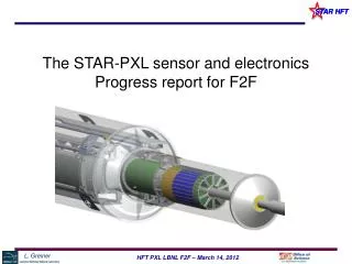
STAR-PXL Mechanical Integration and Cooling St. Odile Ultra-Thin Vertex Detector Workshop 8-Sept-2011 Howard Wieman
PIXEL Work • Eric Anderssen • Mario Cepeda • Leo Greiner • Tom Johnson • Howard Matis • Hans Georg Ritter • Thorsten Stezelberger • Xiangming Sun • Michal Szelezniak • Jim Thomas • Chi Vu ARES Corporation: Darrell Bultman Steve Ney Ralph Ricketts Erik Swensen
Pixel geometry End view 8 cm radius 20 cm 2.5 cm radius Inner layer Outer layer coverage +-1 One of two half cylinders total 40 ladders
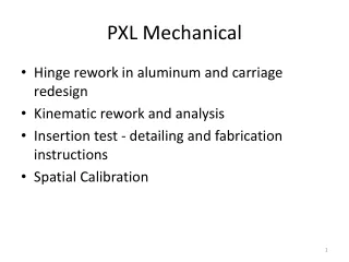
Topics • Mechanical trade offs in achieving the highest pointing precision • Work addressing mechanical precision and stability. • Rapid Detector Replacement
r1 r2 perceived vertex true vertex m x x v v r1 r2 perceived vertex true vertex vertex projection from two points expectations for the HFT pixels pointing resolution = (13 19GeV/pc) m first pixel layer from coulomb scattering from detector position error more than 3 times better than anyone else detector layer 2 detector layer 1
Know where the pixels are • Build a mechanically stable structure • Measure pixel locations – i.e. generate a spatial pixel map that will not be corrupted by mechanical changes
Bob Connors Spiros Margetis Yifei Zhang development of spatial map 10 gm touch probe force touch probe 2-3 m (xyz) and visual 2-3 m (xy) 50 m (z) active volume: huge visual sub micron (xyz) repeatability 5 m accuracy over active volume no touch probe active volume: 30 in X 30 in X 12 in MEMOSTAR3, 30 m pitch
Mechanical Stability Once the pixel positions are measured will they stay in the same place to within 20 µm? Issues that have been addressed: • Movement from temperature changes • Movement from humidity changes • Deflection from gravity • Vibration movement from mounts in STAR • Movement induced by cooling air • how much air is required • vibration and static displacement
Stability requirement drove design choices • The detector ladders are thinned silicon, on a flex kapton/aluminum cable • The large CTE difference between silicon and kapton is a potential source of thermal induced deformation even with modest 10-15 deg C temperature swings • Two methods of control • ALICE style carbon composite sector support beam with large moment of inertia • Soft decoupling adhesive bonding ladder layers Multiple designs were considered. This design optimized low X0, mechanical stability and ease of fabrication
cable bundle drivers kapton flex cable pixel chips adhesive composite backer adhesive wire bonds capacitors Ladder design with soft adhesive (6 psi shear modulus) adhesive: 3M 200MP 2 mil, film adhesive
FEA analysis showing bi-metal thermally induced deformation ladder cross section short direction 20 deg C temperature change rigid bond 500 micron deformation soft adhesive 4.3 micron deformation
FEA analysis of thermally induced deformation of sector beam • FEA shell elements • Shear force load from ladders • 20 deg temperature rise • Soft adhesive coupling • 200 micron carbon composite beam • end cap reinforcement • Maximum deformation 9 microns (30 microns if no end cap)
FEA analysis - sector beam deformation – gravity load • FEA shell analysis • 120 micron wall thickness composite beam • gravity load includes ladders • maximum structure deformation 4 microns • ladder deformation only 0.6 microns
Air cooling of silicon detectors - CFD analysis • Silicon power: 100 mW/cm2 (~ power of sunlight) • 240 W total Si + drivers air flow path – flows along both inside and outside surface of the sector
Air cooling – CFD analysis stream lines with velocity • air flow velocity 9-10 m/s • maximum temperature rise above ambient: 12 deg C • sector beam surface – important component to cooling • dynamic pressure force 1.7 times gravity silicon surface temperature velocity contours
Detector mockup • Kapton cables with copper traces forming heaters allow us to dissipate the expected amount of power in the detector Sensor section ~20 cm Driver section ~6 cm • There are 6 thermistors on each ladder (except for the ladder with silicon chips mounted) that allow us to monitor their temperature with an automated measurement system based on the Touch-1 cable tester • One of the sectors (sector 1) was equipped with 10 dummy silicon chips per ladder, with Pt heaters deposited on top of silicon
Cooling tests at ~360 W – IR images Air 13.8 m/s Hot spots ~37 °C Air 10.1 m/s Hot spots ~41 °C Air 4.7 m/s Hot spots ~48 °C Air temperature ~27 °C
Cooling tests at ~360 W Air temperature ~27 °C Observations: • Mid-section is the hottest part of the ladder • max temperature increase above ambient is ~ 8 °C @ 13.8 m/s ~12 °C @ 10.1 m/s ~17 °C @ 4.7 m/s unsuported end mid-section fixed end Solid – inner layer Open – outer layer
vibration modes – preliminary – better composite numbers available 224 Hz 348 Hz 229 Hz 473 Hz 316 Hz
The message Lots of complicated modes close in frequency End cap raises frequencies a bit vibration modes with reinforced end cap 259 Hz 441 Hz 276 Hz 497 Hz 397 Hz
wind tunnel setup to test vibration and displacement carbon fiber sector beam capacitance vibration probe two positions shown air in air out adjustable wall for air turn around air velocity probe two positions shown C:\Documents and Settings\Howard Wieman\My Documents\aps project\mechanical\PXL phase 1 sept 2008\sector ph1 wind tunnel.SLDASM
wind tunnel, rapid prototype parts from model air flow control parts built with 3D printer parts built with SLA, stereolithography apparatus
capacitive probe vibration measurements air velocity 2.7 m/s position signal, 25 m/volt log FFT, peak at 135 Hz air velocity 9.5 m/s position signal, 25 m/volt
Ladder vibration induced by cooling air no reinforcement at the end system resolution limit all errors desired vibration target required air velocity 18 mph
17 µm 17 µm 6 µm -167 µm 9 µm -179 µm 11 µm -248 µm 1 µm -156 µm -163 µm -113 µm measured static deformation from 9 m/s air flow open end reinforced end
4 µm 6 µm 6 µm 3 µm 3 µm 13 µm 14 µm 2 µm 14 µm 8 µm 4 µm 11 µm measured vibration (RMS) induced by 9 m/s air flow open end reinforced end
Vibrations caused by airflow coupled means that the unsupported end is tied to sector 2 • Sector 1, Ladder 2 (coupled ) (coupled ) (coupled ) Beginning of the driver section (Supported end) End of sensor section (Unsupported end)
Vibration from STAR support, accelerometer measurement • detector vibration from STAR support < 0.1 micron RMS
measurements of thermal sector distortions to be added
end with conclusions rest are backup
Eric Anderssen and Tom Johnson have been working on fabrication methods for: Sector Beam and Ladders Produced sample beams, 244 m thick, 7 ply, 21 gm expected ladder mass 7.5 gm Development of sector beam and ladder fabrication ladders sector beam
ladder fabrication and tooling finalizing mechanical designs and developing rapid production methods
ladder fabrication and tooling ladder with silicon heater chips (50 m thick)