p-bar target
270 likes | 410 Views
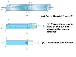
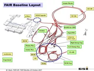
Atomic Physics. FAIR Baseline Layout. SIS 100. SIS18 Upgrade. p-linac. SIS 300. SIS100 SIS300. p-linac. HADES & CBM. PANDA. SuperFRS. Unilac. Antiproton Prod. Target. HESR. HESR. High Energy Exp. Super- FRS. Plasma Phys. Low Energy Exp. p-bar target. Atomic Phys.

p-bar target
E N D
Presentation Transcript
Atomic Physics FAIR Baseline Layout SIS 100 SIS18 Upgrade p-linac SIS 300 SIS100 SIS300 p-linac HADES & CBM PANDA SuperFRS Unilac Antiproton Prod. Target HESR HESR High Energy Exp. Super- FRS Plasma Phys. Low Energy Exp. p-bar target Atomic Phys. FLAIR Accelerator RESR RESR CR CR Experiment NESR Exp. NESR
RIBs to CR pbars to CR stable ions to NESR to low energycomplex FLAIR (ions, pbars) e- linac ER CR NESR pbar and RIB stochastic pre-cooling pbar and iondeceleration experiments with stored ions RESR pbar accumulation (RIB deceleration) The FAIR 13 Tm Storage Rings to HESR
The Collector Ring CR • fast stochastic cooling of • antiprotons (10 s) and • rare isotope beams (1.5 s) • fast bunch rotation at h=1 • with rf voltage 200 kVadiabatic debunching • stochastic pre-cooling system 1-2 GHz • optimized ring lattice (slip factor) • for proper mixing • large acceptance magnet system circumference 214 m magnetic bending power 13 Tm isochronous (RIB) 790 MeV/u 3.56/4.42 0.7 % 70/5010-6 m 1.84 RIB pbar energy 740 MeV/u 3.0 GeV tunes Qx/Qy 3.11/3.10 4.42/4.44 mom. accept. 1.5 % 3.0 % transv. accept. 20010-6 m 24010-6 m transition energy 2.7 3.6 isochronous mass measurementsof rare isotope beams
Fast Bunch Rotation in CR Fast bunch rotation of SIS100 bunchto provide optimum initial parametersfor stochastic cooling total rf voltage 200 kV at h=1 reduces the momentum spread (2.5 0.5 %) after passage of production target SIS100 bunch after target bunch rotation cavity (similar to SIS18 bunch compressor) voltage 40 kV length 1 m frequency range 1.38 – 1.61 MHz rotation time 100 s after bunch rotation anddebunching in CR specified for prototype contract
CR Stochastic Cooling System Fast Stochastic Pre-coolingsystem band width 1-2 GHzmatched to velocities = 0.83 - 0.97rf power ~ 1-2 kW per system increase of impedance (factor of 4) analysis by L. Thorndahl GSI 6 mm air gap 92 mm horizontal electrodeprototype CERN AC, band 1 58 mm horizontal front side back side Frequency [GHz] pick-ups must be installed on movable supports (plungers) with option of cryogenic cooling prototype development in EUFP6
Stochastic Cooling Developments Computer controlled field mapping CR movable electrode installation in vacuum tank including pre-amplifiers operated at 30 K In preparation: vacuum tank cold heads power amplifiers Optimization of voltage and phase flatness
CR Closed orbit correction Number of vertical correctors 18 Number of horizontal correctors 24 + 4 Dipole correctors field variation ± 0.02 T Number of monitors (h/v) 18 Max. deflection angle ± 2.3 mrad Max. mag. field of correctors 0.1 T Eff. Length 0.3 m Good field region 380 x 160 mm2 Field quality ± 5x10⁻³
CR Closed orbit correction MAD and WINAGILE simulations Before correction The most probable COD ≈ 20 mm After correction The most probable COD ≈ 1 mm Orbit corrections are important for optimum stochastic cooling
RESR The Antiproton Accumulator Ring • accumulation of antiprotons by a combination of rf stochastic cooling • max. accumulation rate 7 × 10¹⁰/h max. stack intensity 1× 10¹¹ additional mode: fast deceleration of RIBs to a minimum energy of 100 MeV/u for injection into NESR (collider mode) circumference 248 m magnetic bending power 13 Tm tunes Qx/Qy 3.8/3.3 momentum acceptance 1.0 % transverse accept. h/v 80/3510-6 m transition energy 3.52
New RESR lattice new design old design γ = 4.2 for pbars γ = 1.8 for RIBs inj.kicker extr. kicker Gamma-tr can be adjusted within range of 3.3 – 6.4 by quadrupole magnets Fixedγtr= 3.6 inj.septum extr.septum S.C. pick-up
New RESR Lattice advantages: more flexibility for optics (variable t, option of asymmetric operation) larger transition energy t (3.5 3.3-6.4) reduced circumference (248 240 m) reduced number of quadrupoles ( 44 36) relaxed parameters for injection components (less kicker modules) (kick angle inj./ ext. 11/7 4 mrad, larger separation at septum) drawback: reduced acceptance (long.: 1.0 0. 8 %, horiz./vert. : 80/35 40/30 mm mrad)
Civil Construction of CR/RESR Building Ring Tunnel RESR fits, but building length must be increased
Stochastic Cooling for Antiproton Accumulation partial aperture injection kicker beam deposit stack tail stack core vacuum chamber at momentum pick-up injected beam p/p = 0.5 % p/p = 0.32 % p/p = 0.8 % 160 mm • requirement: • large dispersion and small vertical beta-function at pick-up • proper mixing
NESRVersatile Storage Ring for Physics Experiments Ions storage and cooling of ion beams in the energy range 740 4 MeV/u maximum deceleration rate 1 T/s experiments with internal target luminosity up to 1029 cm-2s-1 RIB accumulation by electron cooling collider mode 1) with electrons luminosity up to 1028 cm-2s-1 2) with antiprotons luminosity up to 1023cm-2s-1 electron target circumference 222.11 m magnetic bending power 13 Tm tunes Qx/Qy 3.4 / 3.2 momentum acceptance 1.75 % transverse accep. h/v 160/10010-6 m length of straight section 18 m Antiprotons deceleration 3000 800 30 MeV electron cooling at 800 MeV
Optimization of NESR Lattice 500 MeV electron linac antiproton injection from RESR to EAR interaction region as bypass allows simplified collision optics old lattice bending section optimized for chromaticity corrections ring circumference unchanged
Optics of New NESR Lattice ring acceptance ex=160 mm mrad ey =40 mm mrad dp/p=+1.5 % for = 0: dp/p=+2.8 % extraction injection
Bypass Mode of NESR NESR ion optical functions ER including sextupole corrections P. Shatunov, D. Shvartz, BINP dynamic aperture in bypass mode is reduced ER dynamic aperture limited by octupole components in quadrupole fringe fields
NESR Electron Cooler design by BINP, Novosibirsk Cooler Parameters energy 2 - 450 keV max. current 2 A beam radius 2.5-14 mm magnetic field gun up to 0.4 T cool. sect. up to 0.2 T straightness 2×10⁻⁵ vacuum 10-11 mbar Issues: • high voltage up to 500 kV • fast ramping, up to 250 kV/s • magnetic field quality
Cooling time calculations with BETACOOL equilibrium between two main competing processes Equilibrium IBS heating rate Cooling rate Evolution of emittances and momentum spread: 132Sn50+ , E = 740 MeV/u, Ni =108 (coasting beam) ne = 3.2 108 cm-3 (Ie=1 A,re=0.5 cm), Bc = 0.2 T, Parkhomchuk model: kTeff,e = 10-3 eV Martini IBS model cooling time forpre-cooled ionsbelow 1 s
Cooling of Hot Secondary Beams strong increase of cooling time for large emittance beams 132 Sn52+ 740 MeV/u e.g. cooling time 1000 s for = 10 mm mrad, p/p = 5 × 10⁻³ cooling time for hot RIBs from SuperFRS cooling time for hot RIBs from SuperFRS cooling time for hot RIBs from SuperFRS cooling time for hot RIBs from SuperFRS cooling time for hot RIBs from SuperFRS total cooling time exceeds 1000 s without stochastic pre-cooling in CR
Electron Cooling of Antiprotons in NESR Simulation with BETACOOL Ei = 800 MeV (Ee = 435 keV) Ie= 2 A, re= 1 cm, B = 0.2 T Cooling time dependenceon initial beam quality 1 (CR) tota l 140 s total 20 s 1.5 m, p/p 1 10-3
Accumulation of Ions at the ESRProof of Principle with B. Franzke, T. Katayama, D. Möhl, G. Schreiber VBB=120 V, TB=200 ns (5 MHz), Ie=100 mA 40Ar18+ 65.3 MeV/u End adiab. debunching 1.5 s Start adiab. debunching 1.25 s ion current injection~1.2 s gap End moving 0.85 s Start moving 0.35 s End adiab. bunching 0.25 s Start adiab. bunching t=0 revolution time Trev=1 μs main goal: benchmarking of simulation tools
Simulation of Barrier Bucket Accumulation in the ESR t = 0.04 s t = 0.04 s t = 0.0 s t = 0.0 s t = 3.2 s t = 1.5 s t = 2.8 s t = 3.1 s t = 3.6 s t = 3.5 s t = 4.0 s t = 3.96 s t = 3.92 s t = 4.0 s ring circumference T. Katayama
t=2.0 s Accumulation of RIBs at NESR Injection Energy Longitudinal stacking with Barrier Buckets (simulations by T. Katayama) 132Sn50+ Ek = 740 MeV/u barrier voltage 2 kV revolution time 0.9 s Continuous cooling with electron beam (1 A) keeps stack cold and merges it with the freshly injected beam
NESR Civil Construction Planning Lower (ring) level Upper level power converters, common systems rf, diagnostics, vacuum, controls Technical components and experiments will be integrated
Storage Ring Concept developed by FAIR Storage Ring Group: Rings, Cooling C. Dimopoulou, A. Dolinskyy, K. Knie, I. Nesmiyan, F. Nolden, D. Obradors-Campos, I. Schurig Stochastic Cooling C. Peschke, S. El-Hanaoui, U. Jandewerth, P. Petri PhD Students A. Gorda, V. Gostishchev many contributions from Accelerator division technical groups, from FAIR-TD and Research groups collaboration with B. Franzke, T. Katayama, D. Möhl, L.Thorndahl, P. Shatunov, D. Shvartz and others from BINP


![final p roject [bar rendering]](https://cdn1.slideserve.com/2337755/final-p-roject-bar-rendering-dt.jpg)