Download
1 / 34
580 likes | 1.18k Views
PH 0101 UNIT-3 LECT - 6. Fiber optics Basic principles Physical structure of optical fibre Propagation characteristics of optical fibre. FIBER OPTICS : The most electronic communication was carried by copper cables, whether twisted pairs, coaxial cables or copper waveguides.

E N D
PH 0101 UNIT-3 LECT - 6 • Fiber optics • Basic principles • Physical structure of optical fibre • Propagation characteristics of optical fibre UNIT III Lecture 6
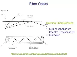
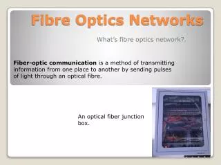
FIBER OPTICS : • The most electronic communication was carried by copper cables, whether twisted pairs, coaxial cables or copper waveguides. • Communication was accomplished by sending electrical signals through the copper cables or waveguides. • In recent years, a new medium has been introduced: Optical fibers. • In optical fiber communication, light signals replace electrical signals. • This branch of science is called fiber optics. UNIT III Lecture 6
PHYSICS OF LIGHT : • The propagation of light can be analyzed in detail using electromagnetic wave theory. • Light falls in the general category of electromagnetic waves, much like radio waves. • The behaviour of light is sometimes easier to explain by using ray tracings • The propagation of light in a fiber can be described in terms of rays. UNIT III Lecture 6
REFLECTION : When a light ray is incident on a reflecting surface, the ray bounces back like a handball when it hits a wall. A reflecting surface is one that is highly polished, opaque and coated with special reflective materials. The law of reflection states that the angle of incidence is equal to the angle of reflection. The incident ray is the line AO, the reflected ray is OB and ON is the normal to the reflecting surface. The incident and reflected angles, 1 and 2, respectively, are those between the rays and the line perpendicular to the surface. UNIT III Lecture 6
INCIDENT AND REFLECTED RAYS UNIT III Lecture 6
The law of reflection states that the angle of incidence is equal to the angle of reflection. the incident ray is the line AO, the reflected ray is OB and ON is the normal to the reflecting surface. • The incident and reflected angles, 1 and 2, respectively, are those between the rays and the line perpendicular to the surface • 1 = 2 • A direct result of this law is the fact that if 1 is 90, 2 is 90 and the reflected ray is in line with the incident ray. UNIT III Lecture 6
REFRACTION AND SNELL’S LAW : When a ray travels across a boundary between two materials with different refractive indices n1and n2, both refraction and reflection takes place. The case where n1 > n2; that is where the light travels from high to low refractive index materials. The refracted ray is “broken” that is, the angle 2 is not equal to 1. The relation between 1 and 2 is given by Snell’s law of refraction. (or) UNIT III Lecture 6
INCIDENT AND REFRACTED RAYS UNIT III Lecture 6
A ray travelling from a high to a low index material will move away from the perpendicular. • The angle of incidence is smaller than the angle of the refracted ray. • The reverse holds for rays travelling from low to high index material. The relation between the incident and refracted angles can be stated in terms of the propagation velocities in the media • Here, the two materials involved are transparent and allow light propagation. and where UNIT III Lecture 6
Total Internal reflection : When 2, the angle of refraction becomes 90, the refracted beam is not traveling through the n2 material. Applying Snell’s law of refraction, The angle of incidence 1 for which 2= 90 is called the critical angle c: UNIT III Lecture 6
REFRACTION AT THE CRITICAL ANGLE UNIT III Lecture 6
If the ray is incident on the boundary between n1 and n2 materials at the critical angle, the refracted ray will travel along the boundary, never entering the n2material. • There are no refracted rays for the case where 1 c. • This condition is known as total internal reflection, which can occur only when light travels from higher refractive index material to lower refractive index material. UNIT III Lecture 6
Contd. • The light can be restricted to the material with the higher index of refraction if the incident angle is kept above the critical angle. • A sandwich of high index material placed between two slabs of low index material will allow a beam of light to propagate in the high index material with relatively little loss. • This concept is used in constructing fibers for fiber optic communication. UNIT III Lecture 6
Solved Problem (1) : Two layers of glass are placed on top of each other. The light is travelling from n = 1.45 to n = 1.40. Find the range of angles , for which total internal reflection takes place. n1 = 1.45 and n2 = 1.40. We know that Substituting the values of n1 and n2 = 74.9 Thus, for the critical case x = 90 – 74.9 = 15.1, and for all angles x less than 15.1, total internal reflection takes place. UNIT III Lecture 6
PHYSICAL STRUCTURE OF OPTICAL FIBER : • An optical fiber is a transparent rod, usually made of glass or clear plastic through which light can propagate. • The light signals travel through the rod from the transmitter to the receiver and can be easily detected at the receiving end of the rod, provided the losses in the fiber are not excessive. • The structure of the modern fiber consists of an optical rod core coated with a cladding. • The core and the cladding have different refractive indices and hence different optical properties UNIT III Lecture 6
Countd. • The refractive index of the core is always greater than that of the cladding (i.e.) n1 > n2. • The light travels within the core by the principle of total internal reflection • An unclad fiber and a clad rod through which the light travels. • With the unclad rod, only a small potion of the light energy is kept inside; most of the light leaks to the surroundings. • The clad fiber is a much more efficient light carrier. UNIT III Lecture 6
Countd. • The losses of the light as it travels through the fiber are much smaller for the clad fiber than for the unclad one. • The thickness of the core of a typical glass fiber is nearly 50 μm and that of cladding is 100 – 200 μm. • The overall thickness of an optical fiber is nearly 125 – 200 μm. • Thus an optical fiber is small in size and light weight unlike a metallic cable. UNIT III Lecture 6
Light guides (a) Simple glass rod (b) Glass rod and cladding with different refraction qualities UNIT III Lecture 6
Propagation characteristics of optical fiber : • Meridinal rays and Skew rays : • The light rays, during the journey inside the optical fiber through the core, cross the core axis. Such light rays are known as meridinal rays. • The passage of such rays in a step index fiber is Similarly, the rays which never cross the axis of the core are known as the skew rays. • Skew rays describe angular ‘helices’ as they progress along the fiber. UNIT III Lecture 6
Countd. • They follow helical path around the axis of fiber. • A typical passage of skew rays in a graded index fiber is shown in the following Fig. • The skew rays will not utilize the full area of the core and they travel farther than meridinal rays and undergo higher attenuation. UNIT III Lecture 6
MERIDINAL AND SKEW RAYS Acceptance Angle : It should be noted that the fiber core will propagate the incident light rays only when it is incident at an angle greater than the critical angle c. The geometry of the launching of the light rays into an optical fiberis shown in the following Fig. UNIT III Lecture 6
Acceptance angle UNIT III Lecture 6
A meridinal ray A is to be incident at an angle a in the core – cladding interface of the fiber. • The ray enters the fiber core at an angle a to the fiber axis. • The ray gets refracted at the air – core interface at angle c and enters into the core – cladding interface for transmission • Therefore, any ray which is incident at an angle greater than a will be transmitted into the core – cladding interface at an angle less than c and hence will not undergo total internal reflection. UNIT III Lecture 6
Contd. • The ray B entered at an angle greater than a and eventually lost propagation by radiation. • It is clear that the incident rays which are incident on fiber core within conical half angle c will be refracted into fiber core, propagate into the core by total internal reflection. • This angle a is called as acceptance angle, defined as the maximum value of the angle of incidence at the entrance end of the fiber, at which the angle of incidence at the core – cladding surface is equal to the critical angle of the core medium. UNIT III Lecture 6
Acceptance cone : The imaginary light cone with twice the acceptance angle as the vertex angle, is known as the acceptance cone. Numerical Aperture (NA) : Numerical aperture (NA) of the fiber is the light collecting efficiency of the fiber and is a measure of the amount of light rays can be accepted by the fiber. UNIT III Lecture 6
Numerical aperture A ray of light is launched into the fiber at an angle 1 is less than the acceptance angle a for the fiber as shown. UNIT III Lecture 6
This ray enters from a medium namely air of refractive index n0to the fiber with a core of refractive index n1which is slightly greater than that of the cladding n2 . Assume that the light is undergoing total internal reflection within the core. Applying Snell’s law of refraction at A, In the triangle ABC, or UNIT III Lecture 6
From the above two equations, When the total internal reflection takes place, θ = θc and θ1 = θa . Therefore, UNIT III Lecture 6
Also, at B, applying the Snell’s law of refraction, we get From the above equation, we get This is called the numerical aperture(N.A). The numerical aperture is also defined as the sine of the half of the acceptance angle. UNIT III Lecture 6
In terms of refractive indicesn1and n2, where n1 is the core index and n2 the cladding index The half acceptance angle a is given by From the above eqns, we get UNIT III Lecture 6
Solved Problem (1) : A fiber has the following characteristics: n1 = 1.35 (core index) and =2%. Find the N.A and the acceptance angle. n1 = 1.35 ; = 2% = 0.02 W.K.T = 1.35 (2 0.02)1/2 = 0.27 a = sin – 1 (N.A) = sin – 1 (0.27) = 15.66 Acceptance angle = 2a = 31.33 UNIT III Lecture 6
Solved Problem (2) : A silica optical fiber has a core refractive index of 1.50 and a cladding refractive index of 1.47. Determine (i) the critical angle at the core – cladding interface, (ii) the N.A for the fiber and (iii) the acceptance angle for the fiber. n1 = 1.50 ; n2 = 1.47 = The critical angle = The numerical aperture The acceptance angle = 2a = 2 sin – 1 (N.A) = 2 sin – 1 (0.30) = 34.9 Critical angle = 78.5º ; N.A = 0.30 ; Acceptance angle = 34.9 UNIT III Lecture 6
Exercise (1) : Calculate the numerical aperture and acceptance angle of fiber with a core index of 1.52 and a cladding index of 1.50. Hint: n1 = 1.52 ; n2 = 1.50 = 0.246 and a = sin – 1 (N.A) = 1414; Acceptance angle = 2a = 2828 UNIT III Lecture 6
Exercise (2) : The relative refractive index difference for an optical fiber is 0.05. If the entrance end of the fiber is facing the air medium and refractive index of core is 1.46, estimate the numerical aperture Hint: n1 = 1.46 ; Δ = 0.05 ; UNIT III Lecture 6