Fiber Optics
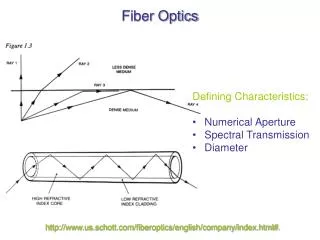
Fiber Optics. Defining Characteristics: Numerical Aperture Spectral Transmission Diameter. http://www.us.schott.com/fiberoptics/english/company/index.html# . Are you getting the concept?. Light of vacuum wavelength l 0 = 850.0 nm enters the end of an optical

Fiber Optics
E N D
Presentation Transcript
Fiber Optics • Defining Characteristics: • Numerical Aperture • Spectral Transmission • Diameter http://www.us.schott.com/fiberoptics/english/company/index.html#.
Are you getting the concept? Light of vacuum wavelength l0= 850.0 nm enters the end of an optical fiber from air at an angle of 20.5o with respect to the normal. Its wavelength inside the fiber is 574.3 nm. A. What is the index of refraction inside the fiber? B. What is the angle between the light ray and the normal inside the fiber? C. Assuming the end of the fiber is perpendicular to its upper edge, what is the angle between the light ray and the surface when the light reaches the upper edge? D. If the index of refraction outside the upper edge of the fiber is 1.44, what is the angle between the light and the normal to the surface as it exits the upper edge?
Numerical Aperture (NA) Cut-off Angle: This maximum value for the angle of incidence on the fiber that experiences TIR is called the cut-off angle. houtside NA: A dimensionless number that characterizes the range of angles over which the system can accept or emit light http://www.us.schott.com/fiberoptics/english/company/index.html#.
Are you getting the concept? Consider an optical fiber having a core index of 1.46 and a cladding index of 1.45.What is the critical angle for this core- cladding interface?For what range of angles inside the fiber at the entrance to the fiber (q2) will light be totally internally reflected at the upper edge of the fiber? To what range of incidence angles (q1) does this correspond? What is the numerical aperture of this fiber?
Are you getting the concept? Consider an optical fiber having a core index of 1.46 and a cladding index of 1.45.What is the critical angle for this core- cladding interface?For what range of angles inside the fiber at the entrance to the fiber (q2) will light be totally internally reflected at the upper edge of the fiber? To what range of incidence angles (q1) does this correspond? What is the numerical aperture of this fiber?
Evanescent Waves in Fiber Optics http://www.olympusmicro.com/primer/java/tirf/evaintensity/ http://www.photonics.cusat.edu/
Evanescent Waves for TIR Microscopy http://www.olympusmicro.com/primer/java/tirf/penetration/index.html
Optics Terminology and Assumptions Focus or focal point – point from which a portion of waves diverge or on which they converge Optical Axis – central axis through optical elements Principle of Reversibility – if source and image are interchanged, the route the light follows is unchanged An object (in object space) is related to an image (in image space) as conjugate points (i.e. the object would be equally well imaged at either point) Real image – a luminous image of the object would appear if a screen was placed at the focus in image space Virtual image – no luminous image of the object would appear if a screen was placed at the focus Eugene Hecht, Optics, Addison-Wesley, Reading, MA, 1998.
Planar Mirrors Front surface mirrors Usually “glass” coated with Al image object Eugene Hecht, Optics, Addison-Wesley, Reading, MA, 1998.
Spherical Mirror Formula Use external angle theorem: exterior angle of a triangle is equal to the sum of the opposite interior angles Make paraxial approximation: Assume 1 is small so that sin1~ 1 (in radians) cosq1 ~ 1 tanq1 ~ q1 Ingle and Crouch, Spectrochemical Analysis
Spherical Mirrors Convex Concave Virtual Image Real Image Eugene Hecht, Optics, Addison-Wesley, Reading, MA, 1998.
Focal Length of Spherical Mirrors + for concave (R<0) - for convex (R>0) Ingle and Crouch, Spectrochemical Analysis General Mirror Formula:
Producing Collimating Light with Spherical Mirrors Ingle and Crouch, Spectrochemical Analysis
Focal Plane Image formed off axis in the focal plane. Useful for separating light traveling at different angles. Ingle and Crouch, Spectrochemical Analysis
Predicting Where Images Will Form Eugene Hecht, Optics, Addison-Wesley, Reading, MA, 1998.
Image Reflected From a Spherical Mirror Transverse Magnification: Mt = -si/so • with the following sign • conventions: • so/si + for real object/image • so/si - for virtual object/image • + Mt signals an erect image • Mt signals an inverted image • |Mt| >1 signals a magnification • |Mt| <1 signals a minification Eugene Hecht, Optics, Addison-Wesley, Reading, MA, 1998.
Are you getting the concept? Describe the geometric conditions that must exist to see a magnified upright image in a spherical mirror.
Lenses We will only consider “thin” lenses where the thickness of the lens is small compared to the object and image distances. http://en.wikipedia.org/wiki/Lens_Maker%27s_Formula Eugene Hecht, Optics, Addison-Wesley, Reading, MA, 1998.
Refraction at a Spherical Surface Uses the paraxial approximation Ingle and Crouch, Spectrochemical Analysis Eugene Hecht, Optics, Addison-Wesley, Reading, MA, 1998.
Biconvex Lens: Overlap of two spheres Ingle and Crouch, SpectrochemicalAnalysis Position of l’: Position of l: Lensmaker’s Formula
Basic Lenses Convex Concave http://en.wikipedia.org/wiki/Lens_Maker%27s_Formula
Lens Makers’ Formula Determining the focal length of a lens: f = focal length n = refractive index of lens material nm = refractive index of surrounding medium R1 = radius of curvature of surface #1 R2 = radius of curvature of surface #2 d = thickness of lens If d << R1, R2, make the thin lens approximation: C f R Eugene Hecht, Optics, Addison-Wesley, Reading, MA, 1998.
C f R Simple Lenses Many different configurations: www. wikipedia.org Sign Conventions for R values:
Are you getting the concept? Calculate the focal length of a planoconvex lens of radius of curvature 60 mm and index of refraction of 1.5 in air using the thin lens approximation.
Parallel Rays Eugene Hecht, Optics, Addison-Wesley, Reading, MA, 1998.
Optical Center Eugene Hecht, Optics, Addison-Wesley, Reading, MA, 1998.
Tracing rays to determine the position of the image. Eugene Hecht, Optics, Addison-Wesley, Reading, MA, 1998.
Off Axis Rays Focus on the Focal Plane http://www.microscopyu.com/tutorials/java/components/perfectlens/index.html
Chromatic Aberrations h is dependent Eugene Hecht, Optics, Addison-Wesley, Reading, MA, 1998.
Achromatic Doublet Ingle and Crouch, Spectrochemical Analysis
Spherical Aberrations Deviation from the paraxial approximation Ingle and Crouch, Spectrochemical Analysis
Field Curvature Image and focal planes are actually spheres Eugene Hecht, Optics, Addison-Wesley, Reading, MA, 1998.
Comatic Aberration (Coma) Axial rays have different optical path lengths in an off-axis system. Eugene Hecht, Optics, Addison-Wesley, Reading, MA, 1998.
Comatic Aberration (Coma) Image has a comet-like tail Eugene Hecht, Optics, Addison-Wesley, Reading, MA, 1998.
Astigmatism Rays in tangential and sagittal planes have different focal points. ft = fcos1 fs = f / cos1 Ingle and Crouch, Spectrochemical Analysis
Lens Stops Aperture Stop Field Stop Ingle and Crouch, Spectrochemical Analysis
Prisms Right Angle Equilateral Pentagonal Dove www.edmundoptics.com
More Wave Guiding www.edmundoptics.com