Fiber Optics
Fiber Optics. BASIC FIBER OPTIC LINK. Fiber Optics. Fiber optic transmission systems consist of a transmitter that takes an electrical signal and converts it into an optical signal from a laser or LED and couples the light into an optical fiber.


Fiber Optics
E N D
Presentation Transcript
Fiber Optics BASIC FIBER OPTIC LINK
Fiber Optics • Fiber optic transmission systems consist of a transmitter that takes an electrical signal and converts it into an optical signal from a laser or LED and couples the light into an optical fiber. • The light from the transmitter is coupled into the fiber with a connector and is transmitted through the fiber cable plant.
Fiber Optics • The optical signal is then coupled to a receiver at the other end where a detector converts the light back into an electrical signal.
Fiber Optics • Each fiber link requires two fiber strands one for transmit and one for receive, this combination makes a duplex link. THE LEADS ARE REVERSED; TX TO RX AND VICE VERSA TO ESTABLISH A COMMUNICATIONS LINK
Fiber Optics • The performance of a fiber optic link is determined by comparing the input power to the output power at the receiver end. • Either too little or too much power at the receiver end will cause high bit error rates (BER). • Too much power causes receiver amplifier saturation that leads to signal distortion, too little power and noise becomes a problem.
Fiber Optics • This receiver power depends on two factors; how much power is launched into the fiber by the transmitter and how much is lost by attenuation in the optical fiber cable plant that connects the transmitter and receiver. • Therefore the fiber cable plant plays a critical role in the performance of the data link and the connector loss accounts for large portion of the attenuated signal.
Fiber Optics • Some common connector loss problems occur from mismatched connector and fiber types. • One manufactures fiber strands may not match a different manufactures fiber strands, This is true of the connectors as well. • The following slide depicts these mismatches.
Fiber Optics • End gaps cause two problems, insertion loss and return loss. The emerging cone of light from the connector will spill over the core of the receiving fiber and be lost. • In addition, the air gap between the fibers causes a reflection when the light encounters the change in refractive index from the glass fiber to the air in the gap.
Fiber Optics • This reflection amounts to about 5% in typical flat polished connectors, and means that no connector with an air gap can have less than 0.3 dB loss. • This reflection is also referred to as back reflection or optical return loss, which can be a problem in laser based systems.
Fiber Optics • Connectors use a number of polishing techniques to insure physical contact of the fiber ends to minimize back reflection. • On mechanical splices, it is possible to reduce back reflection by using non-perpendicular cleaves, which cause back reflections to be absorbed in the cladding of the fiber.
Fiber Optics • The end finish of the fiber must be properly polished to minimize loss. • A rough surface will scatter light and dirt can scatter and absorb light. • Since the optical fiber is so small, typical airborne dirt can be a major source of loss (blowing on connectors to clear debris will contaminate the end finish with breath vapor).
Fiber Optics • Whenever connectors are not terminated, they should be covered to protect the end of the ferrule from dirt. • One should never touch the end of the ferrule, since the oils on one's skin causes the fiber to attract dirt. • Before connection and testing, it is necessary to clean connectors with lint-free wipes moistened with isopropyl alcohol.
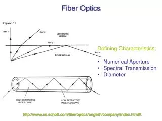
Fiber Optics • Two sources of loss are directional; numerical aperture (NA) and core diameter, differences in these two will create connections that have different losses depending on the direction of light propagation.
Fiber Optics • Numerical aperture is a measure of the light acceptance angle of an optical fiber. • Light from a larger fiber will have high loss coupled to a fiber of smaller diameter, while one can couple a small diameter fiber to a large diameter fiber with minimal loss, since it is much less sensitive to end gap or lateral offset
Fiber Optics • Light from a fiber with a larger NA will be more sensitive to angularity and end gap, so transmission from a fiber of larger NA to one of smaller NA will be higher loss than the reverse. • These fiber mismatches occur for two reasons. The occasional need to interconnect two dissimilar fibers and production variances in fibers of the same nominal dimensions.
Fiber Optics • With two multimode fibers in usage today and two others which have been used occasionally in the past and several types of single mode fiber in use, it is possible to sometimes have to connect dissimilar fibers or use systems designed for one fiber on another.
Fiber Optics • Some system manufacturers provide guidelines on using various fibers, some don't. If you connect a smaller fiber to a larger one, the coupling losses will be minimal, often only the Fresnel loss (about 0.3 dB). • But connecting larger fibers to smaller ones results in substantial losses, not only due to the smaller cores size, but also the smaller NA of most small core fibers
Fiber Optics • Optical loss margin is an important factor in an optical link, this determined by connecting the link with an adjustable attenuator in the cable plant and varying the loss until a S/N (signal to noise) ratio or a BER can be determined. THE TRANS MITTER IS DRIVEN BY A DATA PATTERN GENERATOR AND THE BER FROM THE RECEIVER IS MEASURED TYPICAL SYSTEM FOR DETERMINING MARGIN
Fiber Optics • The optical power margin of the link is determined by two factors; the sensitivity of the receiver which is determined in the bit error rate curve and the output power of the transmitter. The difference between these two power levels determines the transmitted power.
Fiber Optics • The receiver’s sensitivity will determine how well it distinguishes “1s” and “0s” as optical light pulses into it. • This becomes more critical as the bandwidth increases and network speeds reach above 1Gbps.