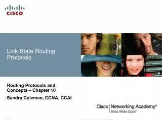
Optimized Link State Routing Protocol
Learn about OLSR, a proactive and table-driven protocol, message and packet format, MPR selection, topology and routing tables. Explore neighbor sensing, link state messaging, and route calculation in OLSR.

Optimized Link State Routing Protocol
E N D
Presentation Transcript
Outline • Brief overview of OLSR • Packet Format and Message Format • Neighbour and link sensing • Multipoint Relays • MPR selection algorithm • TC message • Topology Table • Routing Table
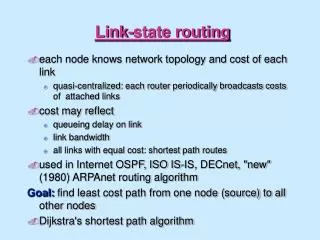
Table driven Source-Initiated On demand DSDV CGSR OLSR TBRPF AODV DSR LMR TORA ABR SSR Ad Hoc Routing Protocols Classification reactive proactive
OptimizedLinkStateRoutingProtocol • Proactive & Table-driven • Link State Routing • Each node expands a spanning tree • Each node can obtain the whole network topology • Utilizes a technique to reduce message flooding • MultiPoint Relaying (MPR)
24 retransmissions to diffuse a message up to 3 hops Retransmission node OptimizedLinkStateRoutingProtocol • Each node periodically floods status of its links • Each node re-broadcasts link state information received from its neighbors • Each node keeps track of link state information received from other nodes • Each node uses above information to determine next hope to each destination
11 retransmission to diffuse a message up to 3 hops Retransmission node - MPR OptimizedLinkStateRoutingProtocol • Only selected neighbors(MultiPointRelays,MPRs)retransmitmessages • Select MPRs such thatthey cover all 2hopneighbors • 2-hopneighbors takenfrom neighbors' HELLOmessages
OptimizedLinkStateRoutingProtocol • Three main modules • Neighbor/link sensing • Provide topology information up to two hops • MPR selector information notification • Optimized flooding/forwarding • MPR set to cover all the two hop neighbors • MPR selector set: set of nodes that select me as one of their MPR set • OLSR-Messages from MPR selector set are to be forwarded • Link-State messaging and route calculation • Topology table • Route table
Packet Format • Packet format contains packet header and message header. • Packet Header: • Packet Length • Packet Sequence Number • Message Header: • Message Type: • Hello Message • TC - Message • MID Message • NHA Message
Packet Format • Message Header: • Vtime: • Vtime indicates for how long time after reception a node MUST consider the information contained in the message as valid. • validity time = C*(1+a/16)* 2^b [in seconds] • a= 4 highest bits of Vtime field. • b= 4 lowest bits of Vtime field. • C= scaling constant and has value 0.0625 sec. • Message Size : • Message counted in bytes and measured from the beginning of the "Message Type" field and until the beginning of the next "Message Type" field.
Packet Format • Message Header: • Originator Address : • Main address of the node, which has originally generated this message. • The Originator Address field never be changed in retransmissions. • Time To Live: • This field contains the maximum number of hops a message will be transmitted. • Before a message is retransmitted, the Time To Live MUST be decremented by 1. • When a node receives a message with a Time To Live equal to 0 or 1, the message would not be retransmitted under any circumstances.
Packet Format • Message Header: • Hop Count: • This field contains the number of hops a message has attained. • Before a message is retransmitted, the Hop Count MUST be incremented by 1. • Initially hop count equal to 1. • Message Sequence Number: • While generating a message, the "originator" node will assign a unique identification number to each message. • The sequence number is increased by 1 (one) for each message originating from the node.
MID Message Format • OLSR Interface Address : • This field contains the address of an OLSR interface of the node, excluding the nodes main address. • All interface addresses other than the main address of the originator node are put in the MID message. • If the maximum allowed message size is reached while there are still interface addresses which have not been inserted into the MIDmessage, more MID messages are generated until the entire interface addresses set has been sent
Hello Message Format • Hello message is sent as the data-portion of the general packet format. • "Message Type" set to HELLO_MESSAGE, • TTL field set to 1 (one) • Vtime set accordingly to the value of NEIGHB_HOLD_TIME. • NEIGHB_HOLD_TIME = 3 x REFRESH_INTERVAL • REFRESH_INTERVAL = 2 seconds.
Hello Message Format • Reserved : • This field must be set to "0000000000000" to be in compliance with this specification. • Htime: • This field specifies the HELLO emission interval. • Time before the transmission of the next HELLO. • HELLO emission interval=C*(1+a/16)*2^b • a is the 4 highest bits of Htime • b is the 4 lowest bits of Htime • C is the scaling factor has value 0.0625 sec.
Hello Message Format • Willingness: • To carry and forward traffic for other nodes. • A node with willingness WILL_NEVER would never be selected as MPR by any node. • A node with willingness WILL_ALWAYS will always be selected as MPR. • By default, a node SHOULD advertise a willingness of WILL_DEFAULT. • The willingness of a node may be set to any integer value from 0 to 7 • Willingness constant: • WILL_NEVER = 0 • WILL_LOW = 1 • WILL_DEFAULT = 3 • WILL_HIGH = 6 • WILL_ALWAYS = 7
HelloMessage Format • Link Code: • This field specifies information about the link between the interface of the sender and the following list of neighbor interfaces. • It also specifies information about the status of the neighbor • Link codes, not known by a node, are silently discarded. • Link Message Size: • The size of the link message, counted in bytes and measured from the beginning of the "Link Code" field and until the next "Link Code" field (or - if there are no more link types - the end of the message). • Neighbor Interface Address: • The address of an interface of a neighbor node.
HELLO Message Generation • A HELLO message serves three independent task: • link sensing • neighbor detection • MPR selection signaling • A HELLO message is therefore generated based on the information stored in the Local Link Set, the Neighbor Set and the MPR Set from the local link information base. • Local link set is of three types. • Symmetric link • A-symmetric link • Lost link
Hello Message Generation • Link set: • The Link Type set according to the following: • if L_SYM_time >= current time (not expired) • Link Type = SYM_LINK • if L_ASYM_time >= current time (not expired) • AND L_SYM_time < current time (expired) • Link Type = ASYM_LINK • if L_ASYM_time < current time (expired) AND • L_SYM_time < current time (expired) • Link Type = LOST_LINK
Hello Message Generation • Neighbor Set: • The Neighbor Type is set according to the following: • If the main address, corresponding to L_neighbor_iface_addr, is included in the MPR set: • Neighbor Type = MPR_NEIGH • if the main address, corresponding to L_neighbor_iface_addr, is included in the neighbor set: • if N_status == SYM • Neighbor Type = SYM_NEIGH • if N_status == NOT_SYM • Neighbor Type = NOT_NEIGH
Neighbour/Link sensing • Link sensing is performed using HELLO message exchange. • A "link" is described by a pair of interfaces: a local and a remote interface. • Each neighbor node (more specifically, the link to each neighbor) has an associated status of either "symmetric" or "asymmetric". • "Symmetric" indicates that the link to that neighbor node has been verified to be bi-directional (means transmission in both directions). • "Asymmetric" indicates that HELLO messages from the node have been heard (for example, communication from the neighbor node is possible), however it is not confirmed that this node is also able to receive messages (for example, communication to the neighbor node is not confirmed).
(Neighbor/Link sensing) con… • A very simplified version of a neighbor discovery session using HELLO messages, is displayed in figure. • A first sends an empty HELLO message. • B receives this message and registers A as an asymmetric neighbor due to the fact that B can not find its own address in the HELLO message. • B then sends a HELLO declaring A as an asymmetric neighbor. • When A receives this message it finds its own address in it and therefore sets B as a symmetric neighbor. • This time A includes B in the HELLO it sends, and B registers A as a symmetric neighbor upon reception of the HELLO message.
Multipoint Relays • Each node N in the network selects a set of neighbor nodes as multipoint relays, MPR(N), that retransmit control packets from N • Neighbors not in MPR(N) process control packets from N, but they do not forward the packets • MPR(N) is selected such that all two-hop neighbors of N are covered by (one-hop neighbors) of MPR(N) One optimal set for Node 4:MPR(4) = { 3, 6 } 4 6 1 7 5 3 2 Is there anotheroptimal MPR(4)? (Assuming bidirectional links)
Multipoint Relay Selector Set • The multipoint relay selector set for Node N, MS(N), is the set of nodes that choose Node N in their multipoint relay set • Only links N-M, for all M such that NMS(M) will be advertised in control messages MS(3) = {…, 4, …} MS(6) = {…, 4, …} 4 6 1 7 5 3 2 (Assuming bidirectional links)
B MPR selection • Each node select a set of MPR Selectors • Who can be a MPR Selectors of node N ? • one-hop neighbors of N • MPR set of Node N (Rules) • Set of MPR’s is able to transmit to all two-hop neighbors • Link between node and it’s MPR is bidirectional. Y N X M D Z A
Multipoint Relays (MPR) • Every node keeps a table of routes to all known destination through its MPR nodes • Every node periodically broadcasts list of its MPR Selectors (instead of the whole list of neighbors). • Upon receipt of MPR information each node recalculates and updates routes to each known destination
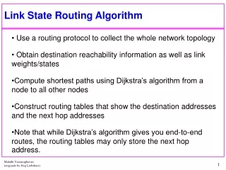
MPR selection algorithm • Each point u has to select its set of MPR. • Goal : Select in the 1-neighborhood of u (N1(u)) a set of nodes as small as possible which covers the whole 2-neighborhood of u(N2(u)). • Step 1: Select nodes of N1(u) which cover isolated points of N2(u). • Step 2: Select among the nodes of N1(u) not selected at the first step, the node which covers the highest number of points of N2(u) and go on till every points of N2(u) are covered.
MPR selection algorithm • First step: Select nodes in N1(u) which cover “isolated points” of N2(u). u
MPR selection algorithm • Final:MPRs u
Multipoint Relays set (MPRs) • Each node uses HELLO messages to determine its MPR set • All nodes periodically broadcast HELLO messages to their one-hop neighbors (bidirectional links) • HELLO messages are not forwarded HELLO: NBR(4) = {1,3,5,6} 4 6 1 7 5 3 2
MPRs) con… • Using the neighbor list in received HELLO messages, nodes can determine their two-hop neighborhood and an optimal (or near-optimal) MPR set • A sequence number is associated with this MPR set • Sequence number is incremented each time a new set is calculated 4 At Node 4: NBR(1) = {2} NBR(3) = {2,5} NBR(5) = {3,6} NBR(6) = {5,7} MPR(4) = {3,6} 6 1 7 5 3 2
(MPRs) con… • Subsequent HELLO messages also indicate neighbors that are in the node’s MPR set • MPR set is recalculated when a change in theone-hop or two-hop neighborhood is detected HELLO: NBR(4) = {1,3,5,6}, MPR(4) = {3,6} 4 MS(6) = {…, 4,…} 6 1 7 5 3 2 MS(3) = {…, 4,…}
TC-Message • Each node, which has been selected as MPR, broadcasts Topology Control (TC) messages. • TC messages are flooded to all nodes in the network and take advantage of MPRs. MPRs enable a better scalability in the distribution of topology information. • A TC message is sent by a node in the network to declare its MPR Selector set. • The information diffused in the network by these TC messages will help each node to calculate its routing table. • A node which has an empty MPR selector set, such as nobody has selected it as a MPR, MUST NOT generate any TC message.
TC message con... 4 6 1 7 5 3 2 MPR(1) = { 4 } MPR(2) = { 3 } MPR(3) = { 4 } MPR(4) = { 3, 6 } MPR(5) = { 3, 4, 6 } MPR(6) = { 4 } MPR(7) = { 6 } MS(1) = { } MS(2) = { } MS(3) = { 2, 4, 5 } MS(4) = { 1, 3, 5, 6 } MS(5) = { } MS(6) = { 4, 5, 7 } MS(7) = { }
TC message con... 4 6 1 7 5 3 2 TC(3) = <2,4,5> • Node 3 generates a TC message advertising nodes in MS(3) = {2, 4, 5} • Node 4 forwards Node 3’s TC message sinceNode 3 MS(4) = {1, 3, 5, 6} • Node 6 forwards TC(3) since Node 4 MS(6)
TC message con... TC(4) = <1,3,5,6> 4 6 1 7 5 3 2 Node 4 generates a TC message advertising nodes in MS(4) = {1, 3, 5, 6} Nodes 3 and 6 forward TC(4) since Node 4 MS(3) and Node 4 MS(6)
TC message con... TC(4) = <1,3,5,6> 4 6 1 7 5 3 2 • Node 6 generates a TC message advertising nodes in MS(6) = {4, 5, 7} • Node 4 forwards TC(6) from Node 6 and Node 3 forwards TC(6) from Node 4 • After Nodes 3, 4, and 6 have generated TC messages, all nodes have link-state information to route to any node
Dest Next Hops 1 4 2 Example(1) source node` 4 6 1 7 5 3 2
Dest Next Hops 2 2 1 Example(1) con… 4 6 1 7 5 3 2
Dest Next Hops 4 4 1 Example(1) con… source node 4 6 1 7 5 3 2
Dest Next Hops 5 5 1 Example(1) con… source node 4 6 1 7 5 3 2
Dest Next Hops 6 4 or 5 2 Example(1) con… source node 4 6 1 7 5 3 2
Dest Next Hops 1 4 2 2 2 1 4 4 1 5 5 1 6 4/ (5) 2 7 4 /(5) 3 Topology Table TC(4) = <1,3,5,6> TC(6) = <4,5,7> 4 6 1 7 5 3 2 TC(3) = <2,4,5> • Given TC information, each node forms a topology table • A routing table is calculated from the topology table.
Example(2).. 4 TC(6) = <5,7> TC(3) = <2,5> node 4 move to an other place 6 1 7 5 3 2 MPR(1) = { 6 } MPR(2) = { 3 } MPR(3) = { 5 } MPR(4) = { } MPR(5) = { 6 } MPR(6) = { 5 } MPR(7) = { 6 } MS(1) = { } MS(2) = { } MS(3) = {2} MS(4) = { } MS(5) = { 3,6} MS(6) = { 1, 5,7 } MS(7) = { }
Dest Next Hops 1 2 2 Example(2).. source node 6 1 7 5 3 2
Dest Next Hops 5 5 1 Example(2) con… Source node 6 1 7 5 3 2