Download
1 / 58
600 likes | 724 Views
This guide covers the essential steps for troubleshooting TCP/IP problems on a Wide Area Network (WAN) using Windows Server 2008 or Windows Vista. It highlights the encapsulation of IP datagrams and Address Resolution Protocol (ARP) messages and provides insights into various WAN technologies, such as T-carrier, PSTN, ISDN, and Frame Relay. Understanding Data Link Layer encodings is crucial for interpreting traffic captured through Microsoft Network Monitor or other WAN monitoring tools. We’ll also explore Point-to-Point Protocol (PPP) and its significance in network encapsulation.

E N D
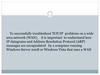
To successfully troubleshoot TCP/IP problems on a wide area network (WAN), it is important to understand how IP datagrams and Address Resolution Protocol (ARP) messages are encapsulated by a computer running Windows Server 2008 or Windows Vista that uses a WAN
technology such as T-carrier, Public Switched Telephone Network (PSTN), Integrated Services Digital Network (ISDN), or Frame Relay.
It is alsoimportant to understand WAN technology encapsulations to interpret the WAN encapsulation portions of a frame when using Microsoft Network Monitor or other types of WAN frame capture programs or facilities.
NoteSupport for Serial Line Internet Protocol (SLIP), X.25, and Asynchronous Transfer Mode(ATM) has been removed from Windows Server 2008 and Windows Vista.
WAN Encapsulations As discussed in Chapter 1, “Local Area Network(LAN) Technologies,” IP datagrams are an Open Systems Interconnection (OSI) Network Layer entity that require a Data Link Layerencapsulation before being sent on a physical medium. For WAN technologies, the Data Link Layer encapsulation provides the following services
Delimitation Frames at the Data Link Layer must bedistinguished from each other,and the frame’s payload must be distinguished from the Data Link Layer header and trailer. • Protocol identification On a multiprotocol WAN link, protocols such as TCP/IP or AppleTalk must be distinguished from each other.
Bit-level integrity check A checksum provides a bit-level integrity check between either the peer nodes on the link or forwarding nodes on a packet-switching network. • Addressing For WAN technologies that support multiple possible destinations using the same physical link, the destination must be identified.
This chapter discusses WAN technologies and their encapsulations for IP datagrams and ARP messages. WAN encapsulations are divided into two categories based on the types of IP networks of the WAN link:
Point-to-point links support an IP network segment with a maximum of two nodes.These links include analog phone lines, ISDN lines, Digital Subscriber Line (DSL) lines,and T-carrier links such as T-1, T-3, Fractional T-1, E-1, and E-3. Point-to-point links do not require Data Link Layer addressing. • Non-broadcast multiple access (NBMA) links support an IP network segment with more than two nodes; however, there is no facility to broadcast a single IP datagram to multiple locations. NBMA links include packet-switching WAN technologies such as Frame Relay. NBMA links require Data Link Layer addressing.
Point-to-Point Protocol The Point-to-Point Protocol (PPP) is a standardized point-to-point network encapsulation method that provides Data Link Layer functionality comparable to LAN encapsulations. PPP provides frame delimitation, protocol identification, and bit-level integrity services. PPP is defined in RFC 1661. More Info All of the RFCs referenced in this chapter can be found in the\Standards\Chap02_WAN folder on the companion CD-ROM.
RFC 1661 describes PPP as a suite of protocols that provide the following: • A Data Link Layer encapsulation method that supports multiple protocols simultaneouslyon the same link. • A protocol for negotiating the Data Link Layer characteristics of the point-to-point connection named the Link Control Protocol (LCP).
A series of protocols for negotiating the Network Layer properties of Network Layer protocols over the point-to-point connection named Network Control Protocols (NCPs). For example, RFCs 1332 and 1877 describe the NCP for IP called Internet Protocol Control Protocol (IPCP). IPCP is used to negotiate an IP address, the addresses of name servers, and the use of the Van Jacobsen TCP compression protocol. This chapter discusses only the Data Link Layer encapsulation. Chapter 4, “Point-to-Point Protocol (PPP),” describes LCP and the NCPs needed for IP connectivity.
PPP encapsulation and framing is based on the International Organization for Standardization (ISO) High-Level Data Link Control (HDLC) protocol. HDLC was derived from the Synchronous Data Link Control (SDLC) protocol developed by IBM for the Systems Network Architecture (SNA) protocol suite. HDLC encapsulation for PPP frames is described in RFC 1662. Figure 2-1 shows HDLC encapsulation for PPP frames.
The fields in the PPP header and trailer are defined as follows: • Flag A 1-byte field set to the FLAG character, 0x7E (bit sequence 01111110), that indicates the start and end of a PPP frame.
Address A 1-byte field that is a by-product of HDLC. In HDLC environments, the Address field is used as a destination address on a multipoint network. PPP links arepoint-to-point, and the destination node is always the other node on the point-to-point link. Therefore, the Address field for PPP encapsulation is set to 0xFF—the broadcast address.
Control A 1-byte field that is also an HDLC by-product. In HDLC environments, the Control field is used to implement sequencing and acknowledgments to provide Data Link Layer reliability services. For session-based traffic, the Control field is more than 1 byte long. For datagram traffic, the Control field is 1 byte long and set to 0x03 to indicate an unnumbered information (UI) frame. Because PPP does not provide reliable Data Link Layer services, PPP frames are always UI frames. Therefore, PPP frames always use a 1-byte Control field set to 0x03.
Protocol A 2-byte field used to identify the upper layer protocol of the PPP payload. For example, 0x00-21 indicates an IP datagram and 0x00-29 indicates an AppleTalk datagram. For the current list of PPP protocol numbers, see. • Frame Check Sequence (FCS) A 2-byte field used to provide bit-level integrity services for the PPP frame. The sender calculates the FCS, which is then placed in the FCS field. The receiver performs the same FCS calculation and compares its result with the result stored in this field. If the two FCS values match, the PPP frame is considered valid and is processed further. If the two FCS values do not match, the PPP frame is silently discarded.
The HDLC encapsulation for PPP frames is also used for Asymmetric Digital Subscriber Line (ADSL) broadband Internet connections. Figure 2-2 shows a typical PPP encapsulation for an IP datagram when using Address and Control field suppression and Protocol field compression.
This abbreviated form of PPP encapsulation is a result of the following: • Because the Address field is irrelevant for point-to-point links, in most cases the PPP peers agree during LCP negotiation to not include the Address field. This is done through the Address and Control Field Compression LCP option.
Because the Control is always set to 0x03 and provides no other service, in most cases the PPP peers agree during LCP negotiation to not include the Control field. This, too, is done through the Address and Control Field Compression LCP option. • Because the high-order byte of the PPP Protocol field for Network Layer protocols suchas IP or AppleTalk is always set to 0x00, in most cases the PPP peers agree during LCP negotiation to use a 1-byte Control field. This is done through the Protocol Compression LCP option.
Note PPP frames captured with Network Monitor do not display the HDLC structure, as shown in Figures 2-1 and 2-2. PPP control frames contain simulated source and destination media access control (MAC) addresses and only the PPP Protocol field. PPP data frames contain a simulated Ethernet II header.
PPP on Asynchronous Links PPP on asynchronous links such as analog phone lines uses character stuffing to prevent the occurrence of the FLAG (0x7E) character within the PPP payload. The FLAG character is escaped, or replaced, with a sequence beginning with another special character called the ESC (0x7D) character. The PPP ESC character has no relation to the ASCII ESC character.
If the FLAG character occurs within the original IP datagram, it is replaced with the sequence 0x7D-5E. To prevent the misinterpretation of the ESC character by the receiving node, if the ESC (0x7D) character occurs within the original IP datagram, it is replaced with the sequence 0x7D-5D. Therefore: • FLAG characters can occur only at the beginning and end of the PPP frame. • On the sending node, PPP replaces the FLAG character within the IP datagram with the sequence 0x7D-5E. On the receiving node, the 0x7D-5E sequence is translated back to 0x7E.
On the sending node, PPP replaces the ESC character within the PPP frame with the sequence 0x7D-5D. On the receiving node, the 0x7D-5D sequence is translated back to 0x7D. If the IP datagram contains the sequence 0x7D-5E, the escaping of the ESC character turns this sequence into 0x7D-5D-5E to prevent the receiver from misinterpreting the 0x7D-5E sequence as 0x7E.
Additionally, character stuffing is used to stuff characters with values less than 0x20 (32 in decimal notation) to prevent these characters from being misinterpreted as control characters when software flow control is used over asynchronous links. The escape sequence for these characters is 0x7D-x, where x is the original character with the fifth bit set to 1. The fifth bit is defined as the third bit from the high-order bit using the bit position designation of 7-6-5-4-3-2-1-0. Therefore, the character 0x11 (bit sequence 0-0-0-1-0-0-0-1) would be escaped to the sequence 0x7D-31 (bit sequence 0-0-1-1-0-0-0-1).
The use of character stuffing for characters less than 0x20 is negotiated using the Asynchronous Control Character Map (ACCM) LCP option. This LCP option uses a 32-bit bitmap to indicate exactly which character values need to be escaped. For more information on the ACCM LCP option, see RFCs 1661 and 1662.
PPP on Synchronous Links Character stuffing is an inefficient method of escaping the FLAG character. If the PPP payload consists of a stream of 0x7E characters, character stuffing roughly doubles the size of the PPP frame as it is sent on the medium. For asynchronous, byte-boundary media such as analog phone lines, character stuffing is the only alternative.
On synchronous links such as T-carrier, ISDN, and Synchronous Optical Network (SONET), a technique called is used to mark the location of the FLAG character. Recall that the FLAG character is 0x7E, or the bit sequence 01111110. With bit stuffing, the only time six 1 bits in a row are allowed is for the FLAG character as it is used to mark the start and end of a PPP frame. Throughout the rest of the PPP frame, if there are five 1 bits in a row, a 0 bit is inserted into the bit stream by the synchronous link hardware. Therefore, the bit sequence
111110 is stuffed to produce 1111100 and the bit sequence 111111 is stuffed to become 1111101. Therefore, six 1 bits in a row cannot occur except for the FLAG character when it is used to mark the start and end of a PPP frame. If the FLAG character does occur within the PPP frame, it is bit stuffed to produce the bit sequence 011111010. Bit stuffing is much more efficient than character stuffing. If stuffed, a single byte becomes 9 bits, not 16 bits, as is the case with character stuffing. With synchronous links and bit stuffing, data sent no longer falls along bit boundaries. A single byte sent can be encoded as either 8 or 9 bits, depending on the presence of a 11111 bit sequence within the byte.
PPP Maximum Receive Unit The maximum-sized PPP frame, the maximum transmission unit (MTU) for a PPP link, is known as the Maximum Receive Unit (MRU). The default value for the PPP MRU is 1500 bytes. The MRU for a PPP connection can be negotiated to a lower or higher value using the Maximum Receive Unit LCP option. If an MRU is negotiated to a value lower than 1500 bytes, a 1500-byte MRU must still be supported in case the link has to be resynchronized.
PPP Multilink Protocol The PPP Multilink Protocol (MP) is an extension to PPP defined in RFC 1991 that allows you to bundle or aggregate the bandwidth of multiple physical connections. It is supported by Windows Server 2008 and Windows Vista Network Connections and the Windows Server 2008 Routing and Remote Access service. MP takes multiple physical connections and makes them appear as a single logical link. For example, with MP, two analog phone lines operating at 28.8 Kbps appear as a single connection operating at 57.6 Kbps. Another example is the aggregation of multiple channels of an ISDN Basic Rate Interface (BRI) or Primary Rate Interface (PRI) line. In the case of a BRI line, MP makes the two 64-Kbps BRI B-channels appear as a single connection operating at 128 Kbps.
MP is an extra layer of encapsulation that operates within a PPP payload. To identify an MP packet, the PPP Protocol field is set to 0x00-3D. The payload of an MP packet is a PPP frame or the fragment of a PPP frame. If the size of the PPP payload that would be sent on a singlelink PPP connection, plus the additional MP header, is greater than the MRU for the specific physical link over which the MP packet is sent, MP fragments the PPP payload.
MP fragmentation divides the PPP payload along boundaries that will fit within the link’s MRU. The fragments are sent in sequence using an incrementing sequence number, and flags are used to indicate the first and last fragments of an original PPP payload. A lost MP fragment causes the entire original PPP payload to be silently discarded. MP encapsulation has two different forms: the long sequence number format (shown in Figure2-3) and the short sequence number format. The long sequence number format adds 4 bytes of overhead to the PPP payload.
The fields in the MP long sequence number format header are defined as follows: • Beginning FragmentBit Set to 1 on the first fragment of a PPP payload and to 0 on all other PPP payload fragments. • Ending Fragment Bit Set to 1 on the last fragment of a PPP payload and to 0 on all other PPP payload fragments. If a PPP payload is not fragmented, both the Beginning Fragment Bit and Ending Fragment Bit are set to 1. • Reserved Set to 0.
Sequence Number Set to an incrementally increasing number for each MP payload sent. For the long sequence number format, the Sequence Number field is 3 bytes long. The Sequence Number field is used to number successive PPP payloads that would normally be sent over a single-link PPP connection and is used by MP to preserve the packet sequence as sent by the PPP peer. Additionally, the Sequence Number field is used to number individual fragments of a PPP payload so that the receiving node can detect a fragment loss.
Figure 2-4 shows the short sequence number format, which adds 2 bytes of overhead to the PPP payload. The short sequence format has only 2 reserved bits, and its Sequence Number field is only 12 bits long. The long sequence number format is used by default unless the Short Sequence Number Header Format LCP option is used during the LCP negotiation.
Frame Relay When packet-switching networks were first introduced, they were based on existing analog copper lines that experienced a high number of errors. The X.25 packet-switched technology was designed to compensate for these errors and provide connection-oriented reliable data transfer. In these days of high-grade digital fiber-optic lines, there is no need for the overhead associated with X.25. Frame Relay is a packet-switched technology similar to X.25, but without the added framing and processing overhead to provide guaranteed data transfer. Unlike X.25, Frame Relay does not provide link-to-link reliability. If a frame in the Frame Relay network is corrupted in any way, it is silently discarded. Upper layer communication protocols such as TCP must detect and recover discarded frames.
A key advantage Frame Relay has over private-line facilities, such as T-Carrier, is that Frame Relay customers can be charged based on the amount of data transferred, instead of the distance between the endpoints. It is common, however, for the Frame Relay vendor to charge a fixed monthly cost. In either case Frame Relay is distance-insensitive. A local connection, such as a T-1 line, to the Frame Relay vendor’s network is required. Frame Relay allows widely separated sites to exchange data without incurring long-haul telecommunications costs.
Frame Relay is a packet-switching technology defined in terms of a standardized interface between user devices (typically routers) and the switching equipment in the vendor’s network (Frame Relay switches). Typical Frame Relay service providers currently only offer permanent virtual circuits (PVCs). A PVC is a path through a packet-switching network that is statically programmed into the switches.
The Frame Relay service provider establishes the PVC when the service is ordered. A new standard for a switched virtual circuit (SVC) version of Frame Relay uses the ISDN signaling protocol as the mechanism for establishing the virtual circuit. An SVC is a path through a packet-switching network that is negotiated using a signaling protocol each time a connection is initiated. This new standard is not widely used in production networks.
Frame Relay speeds range from 56 Kbps to 1.544 Mbps. The required throughput for a given link determines the committed information rate (CIR). The CIR is the throughput guaranteed by the Frame Relay service provider. Most Frame Relay service providers allow a customer to transmit bursts above the CIR for short periods of time. Depending on congestion, the bursted traffic can be delivered by the Frame Relay network. However, traffic that exceeds the CIR is delivered on a best-effort basis only. This flexibility allows for network traffic spikes without dropping frames.
Frame Relay Encapsulation Frame Relay encapsulation of IP datagrams is based on HDLC, as RFC 2427 describes. Because Frame Relay was designed for multiple protocols, Frame Relay encapsulation uses a Network Layer Protocol Identifier (NLPID) field to identify the payload. IP datagrams are encapsulated with a NLPID field set to 0xCC and a Frame Relay header and trailer. Figure 2-5 shows the Frame Relay encapsulation for IP datagrams.
The fields in the Frame Relay header and trailer are defined as follows: • Flag As in PPP frames, the Flag field is 1 byte long and is set to 0x7E to mark the beginning and end of the Frame Relay frame. Bit stuffing is used on synchronous links to prevent the occurrence of the Flag character within the Frame Relay payload.
Address The Address field is multiple bytes long (typically 2 bytes) and contains the Frame Relay virtual circuit identifier called the Data Link Connection Identifier (DLCI) and congestion indicators. The Address field’s structure is discussed in the section titled “Frame Relay Address Field,” later in this chapter.
■Control A 1-byte field set to 0x03 to indicate a UI frame.■NLPID A 1-byte field set to 0xCC to indicate an IP datagram.■Frame Check Sequence A 2-byte CRC used for bit-level integrity verification in the Frame Relay frame. If a Frame Relay frame fails integrity verification, it is silently discarded.
The Frame Relay Address field can be 1, 2, 3, or 4 bytes long. Typical Frame Relay implementations use a 2-byte Address field, as shown in Figure 2-6. Frame Relay Address Field
The fields within the 2-byte Address field are defined as follows: • DLCI The first 6 bits of the first byte and the first 4 bits of the second byte comprise the 10-bit DLCI. The DLCI is used to identify the Frame Relay virtual circuit over which the Frame Relay frame is traveling. The DLCI is only locally significant. Each Frame Relay switch changes the DLCI value as it forwards the Frame Relay frame. The devices at each end of a virtual circuit use a different DLCI value to identify the same virtual circuit.Table 2-1 lists the defined values for the DLCI.