Download
1 / 41
410 likes | 446 Views
Learn about the Internet Protocol (IP) service model, addressing, forwarding, and comparison with ATM. Explore hierarchical addressing, subnetting, and NAT implementation in IP networking.

E N D
IP overview • Service model • Addressing • Forwarding (Routing later)
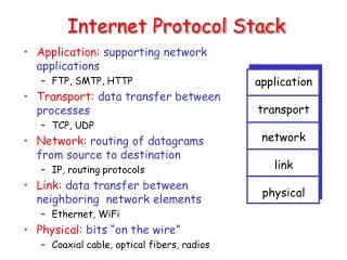
Layer reminder • Bridges - emulate single link • Everything broadcast • Same collision domain • Switches - emulate single network • Flat addressing • Broadcast supported • Internet - connect multiple networks • Hierarchical addressing • No broadcast • Highly scalable
IP service model • Service provided to transport layer (TCP, UDP) • Global name space • Host-to-host connectivity (connectionless) • Best-effort packet delivery • Not in IP service model • Delivery guarantees on bandwidth, delay or loss • Delivery failure modes • Packet delayed for a very long time • Packet loss • Packet delivered more than once • Packets delivered out of order
IP addressing • Ethernet address space • Flat • Assigned at manufacture time • IP address space • Hierarchical • Assigned at configuration time
IP address: 32-bit identifier for host, router interface interface: connection between host/router and physical link routers typically have multiple interfaces host typically has one interface IP addresses associated with each interface 223.1.1.2 223.1.2.1 223.1.3.27 223.1.3.1 223.1.3.2 223.1.2.2 IP Addressing: introduction 223.1.1.1 223.1.1.4 223.1.2.9 223.1.1.3 223.1.1.1 = 11011111 00000001 00000001 00000001 223 1 1 1
Address has 2 components Network (high-order bits) Host (low-order bits) 223.1.1.2 223.1.2.2 223.1.2.1 223.1.3.2 223.1.3.1 223.1.3.27 IP networks 223.1.1.1 223.1.1.4 223.1.2.9 223.1.1.3
Class A: 0 Network (7 bits) Host (24 bits) 1 0 Class B: Network (14 bits) Host (16 bits) 1 1 0 Class C: Network (21 bits) Host (8 bits) IPv4 Address Model
IP networks • Class A network: 18.0.0.0 (MIT) • www.mit.edu has address 18.7.22.83 • Class B network: 128.174.0.0 (UIUC) • www.cs.uiuc.edu has address 128.174.252.84 • Class C network: 216.125.249.0 (Parkland) • www.parkland.edu has address 216.125.249.97
CIDR • 3-class model too inflexible • CIDR: Classless InterDomain Routing • Arbitrary number of bits to specify network • Address format: a.b.c.d/x, where x is # bits in network portion host part subnet part 11001000 00010111 00010000 00000000 200.23.16.0/23
Classless Domains • Internet Archive - 207.241.224.0/20 • 4K hosts • 207.241.224.0 - 207.241.239.255 • AT&T - 204.127.128.0/18 • 16K hosts • 204.127.128.0 - 204.127.191.255 • UUNET - 63.64.0.0/10 • 4M hosts • 63.64.0.0 - 63.127.255.255
IP forwarding • Forwarding table has: • Network number • Interface • Avoid having to store 4 billion entries • But there are still 2 million class C’s • …and perhaps more CIDR networks
200.23.16.0/23 200.23.18.0/23 200.23.30.0/23 200.23.20.0/23 . . . . . . Hierarchical Networks Organization 0 Organization 1 “Send me anything with addresses beginning 200.23.16.0/20” Organization 2 Fly-By-Night-ISP Internet Organization 7 “Send me anything with addresses beginning 199.31.0.0/16” ISPs-R-Us
Subnetting • UIUC - 130.126.0.0/16 • 130.126.0.0 - 130.126.255.255 • CRHC - 130.126.136.0/21 • 130.126.136.0 - 130.126.143.255 • EWS - 130.126.160.0/21 • 130.126.160.0 - 130.126.167.255
Forwarding Tables Internet 130.126.136.0/21 if1 130.126.160.0/21 if2 130.126.0.0/16 if3 0.0.0.0/0 if4 • Most specific rule is used • Most hosts outside of the core have default rules CRHC if1 if4 if2 EWS if3 UIUC
NAT: Network Address Translation rest of Internet local network (e.g., home network) 10.0.0/24 10.0.0.1 10.0.0.4 10.0.0.2 138.76.29.7 10.0.0.3 All datagrams leaving local network have same single source NAT IP address: 138.76.29.7, different source port numbers Datagrams with source or destination in this network have 10.0.0/24 address for source, destination (as usual)
NAT: Network Address Translation • Motivation: local network uses just one IP address as far as outside world is concerned: • range of addresses not needed from ISP: just one IP address for all devices • can change addresses of devices in local network without notifying outside world • can change ISP without changing addresses of devices in local network • devices inside local net not explicitly addressable, visible by outside world (a security plus).
NAT: Network Address Translation Implementation: NAT router must: • outgoing datagrams:replace (source IP address, port #) of every outgoing datagram to (NAT IP address, new port #) . . . remote clients/servers will respond using (NAT IP address, new port #) as destination addr. • remember (in NAT translation table) every (source IP address, port #) to (NAT IP address, new port #) translation pair • incoming datagrams:replace (NAT IP address, new port #) in dest fields of every incoming datagram with corresponding (source IP address, port #) stored in NAT table
3 1 2 4 S: 10.0.0.1, 3345 D: 128.119.40.186, 80 S: 138.76.29.7, 5001 D: 128.119.40.186, 80 1: host 10.0.0.1 sends datagram to 128.119.40.186, 80 2: NAT router changes datagram source addr from 10.0.0.1, 3345 to 138.76.29.7, 5001, updates table S: 128.119.40.186, 80 D: 10.0.0.1, 3345 S: 128.119.40.186, 80 D: 138.76.29.7, 5001 NAT: Network Address Translation NAT translation table WAN side addr LAN side addr 138.76.29.7, 5001 10.0.0.1, 3345 …… …… 10.0.0.1 10.0.0.4 10.0.0.2 138.76.29.7 10.0.0.3 4: NAT router changes datagram dest addr from 138.76.29.7, 5001 to 10.0.0.1, 3345 3: Reply arrives dest. address: 138.76.29.7, 5001
NAT: Network Address Translation • 16-bit port-number field: • 60K simultaneous connections with a single LAN-side address! • NAT is controversial: • routers should only process up to layer 3 • violates end-to-end argument • NAT possibility must be taken into account by app designers, eg, P2P applications • address shortage should instead be solved by IPv6
IPv4 Address Translation support • IP addresses to LAN physical addresses • Problem • An IP route can pass through many physical networks • Data must be delivered to destination’s physical network • Hosts only listen for packets marked with physical interface names • Each hop along route • Destination host
IP to Physical Address Translation • Hard-coded • Encode physical address in IP address • Ex: Map Ethernet addresses to IP addresses • Makes it impossible to associate address with topology • Fixed table • Maintain a central repository and distribute to hosts • Bottleneck for queries and updates • Automatically generated table • Use ARP to build table at each host • Use timeouts to clean up table
ARP • Check table for physical address • If address not present • Broadcast a query, include host’s translation • Wait for a response • Upon receipt of ARP query/response • Targeted host responds with address translation • If address already present • Refresh entry and reset timeout • If address not present • Add entry for requesting host • Ignore for other hosts • Timeout and discard entries after O(10) minutes
ARP Packet 0 8 16 31 Hardware type = 1 ProtocolType = 0x0800 HLEN = 48 PLEN = 32 Operation SourceHardwareAddr (bytes 0 –3) SourceHardwareAddr (bytes 4 – 5) SourceProtocolAddr (bytes 0 – 1) SourceProtocolAddr (bytes 2 – 3) TargetHardwareAddr (bytes 0 – 1) TargetHardwareAddr (bytes 2 – 5) TargetProtocolAddr (bytes 0 – 3)
IP Packet Format 0 4 8 16 19 31 TOS Length Version HLen Ident Flags Offset TTL Protocol Checksum SourceAddr DestinationAddr Pad Options (variable) (variable) Data
IP Packet Format • 4-bit version • IPv4 = 4, IPv6 = 6 • 4-bit header length • Counted in words, minimum of 5 • 8-bit type of service field (TOS) • Mostly unused • 16-bit data length • Counted in bytes
IP Packet Format • Fragmentation support • 16-bit packet ID • All fragments from the same packet have the same ID • 3-bit flags • 1-bit to mark last fragment • 13-bit fragment offset into packet • Counted in 8-byte words • 8-bit time-to-live field (TTL) • Hop count decremented at each router • Packet is discard if TTL = 0
IP Packet Format • 8-bit protocol field • TCP = 6, UDP = 17 • 16-bit IP checksum on header • 32-bit source IP address • 32-bit destination IP address • Options • Variable size • Source-based routing • Record route • Padding • Fill to 32-bit boundaries
IP Packet Size • Problem • Different physical layers provide different limits on frame length • Maximum transmission unit (MTU) • Source host does not know minimum value • Especially along dynamic routes
IP Fragmentation and Reassembly • Solution • When necessary, split IP packet into acceptably sized packets prior to sending over physical link • Questions • Where should reassembly occur? • What happens when a fragment is damaged/lost?
IP Fragmentation and Reassembly • Fragments are self-contained IP datagrams • Reassemble at destination to minimize refragmentation • Drop all fragments in packet if one or more fragments are lost • Avoid fragmentation at source host • Transport layer should send packets small enough to fit into one MTU of local physical network • Must consider IP header • Note: MTU in ATM is based on CS-PDU size
Start of header Ident = x 0 Offset 0 Rest of header H1 R1 R2 R3 H2 1400 data bytes ETH FDDI PPP ETH Start of header Ident = x 1 Offset 0 Rest of header 512 data bytes ETH ETH ETH PPP FDDI PPP PPP ETH IP IP IP IP IP IP IP IP (376) (512) (512) (512) (512) (1400) (1400) (376) Start of header Ident = x 1 Offset 512 Rest of header 512 data bytes Start of header Ident = x 0 Offset 1024 Rest of header 376 data bytes IP Fragmentation and Reassembly
FTP HTTP NV TFTP TCP UDP IP ICMP Ethernet FDDI ATM Modem Internet Control Message Protocol (ICMP) • IP companion protocol • Handles error and control messages
ICMP • Error Messages • Host unreachable • Reassembly failed • IP checksum failed • TTL exceeded (packet dropped) • Invalid header • Control Messages • Echo/ping request and reply • Echo/ping request and reply with timestamps • Route redirect
Source sends series of UDP segments to dest First has TTL =1 Second has TTL=2, etc. Unlikely port number When nth datagram arrives to nth router: Router discards datagram And sends to source an ICMP message (type 11, code 0) Message includes name of router& IP address When ICMP message arrives, source calculates RTT Traceroute does this 3 times Stopping criterion UDP segment eventually arrives at destination host Destination returns ICMP “host unreachable” packet (type 3, code 3) When source gets this ICMP, stops. Traceroute and ICMP
Host Configuration • Plug new host into network • How much information must be known? • What new information must be assigned? • How can process be automated? • Some answers • Host needs an IP address (must know it) • Host must also • Send packets out of physical (direct) network • Thus needs physical address of router
Host Configuration • Reverse Address Resolution Protocol (RARP) • Translate physical address to IP address • Used to boot diskless hosts • Host broadcasts request to boot • RARP server tells host the host’s own IP address • Boot protocol (BOOTP) • Use UDP packets for same purpose as RARP • Allows boot requests to traverse routers • IP address of BOOTP server must be known • Also returns file server IP, subnet mask, and default router for host
Dynamic Host Configuration Protocol (DHCP) • A simple way to automate configuration information • Network administrator does not need to enter host IP address by hand • Good for large and/or dynamic networks
Dynamic Host Configuration Protocol (DHCP) • New machine sends request to DHCP server for assignment and information • Server receives • Directly if new machine given server’s IP address • Through broadcast if on same physical network • Via DHCP relay nodes that forward requests onto the server’s physical network • Server assigns IP address and provides other info • Can be made secure (present signed request or just a “valid” physical address)
DHCP Server Host A DHCP Relay Host A broadcasts DHCPDISCOVER message Host A broadcasts DHCP request Relay unicasts DHCP request to server Server responds with host’s IP address Host B DHCP Server Other Networks DHCP