Download
1 / 5
120 likes | 336 Views
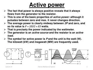
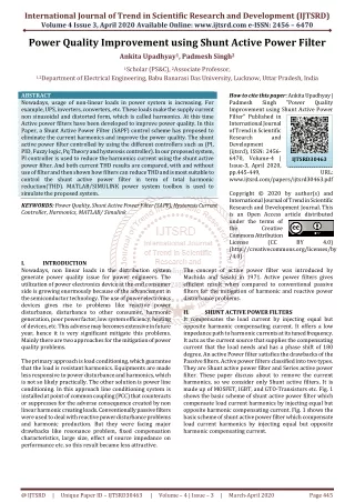
Nowadays, usage of non linear loads in power system is increasing. For example, UPS, inverters, converters, etc. These loads make the supply current non sinusoidal and distorted form, which is called harmonics. At this time Active power filters have been developed to improve power quality. In this Paper, a Shunt Active Power Filter SAPF control scheme has proposed to eliminate the current harmonics and improve the power quality. The shunt active power filter controlled by using the different controllers such as PI, PID, Fuzzy logic, Pq Theory and hysteresis controller . In our proposed system, PI controller is used to reduce the harmonics current using the shunt active power filter. And both current THD results are compared, with and without use of filter and then shown how filters can reduce THD and is most suitable to control the shunt active power filter in term of total harmonic reduction THD . MATLAB SIMULINK power system toolbox is used to simulate the proposed system. Ankita Upadhyay | Padmesh Singh "Power Quality Improvement using Shunt Active Power Filter" Published in International Journal of Trend in Scientific Research and Development (ijtsrd), ISSN: 2456-6470, Volume-4 | Issue-3 , April 2020, URL: https://www.ijtsrd.com/papers/ijtsrd30463.pdf<br>Paper Url :https://www.ijtsrd.com/engineering/electrical-engineering/30463/power-quality-improvement-using-shunt-active-power-filter/ankita-upadhyay

E N D
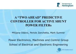
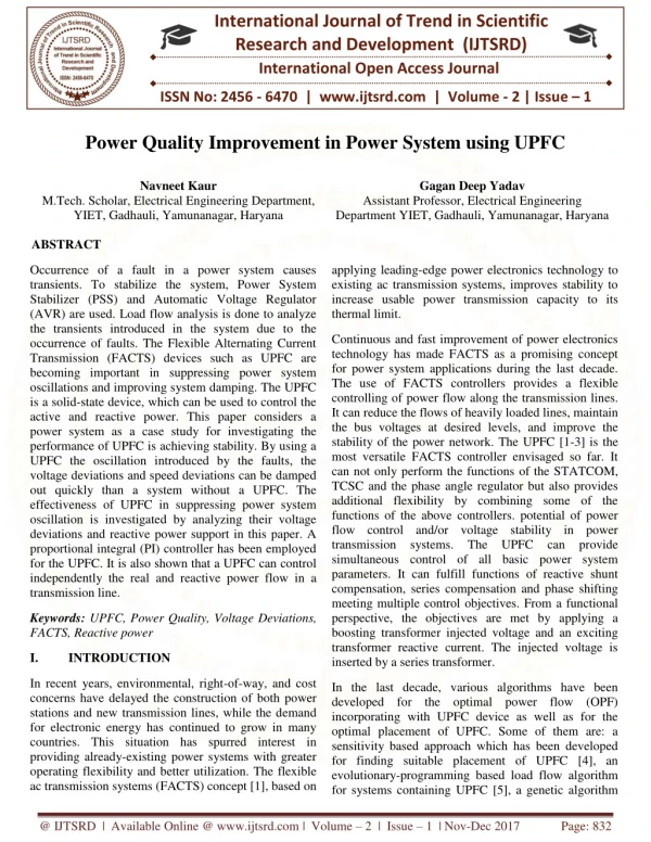
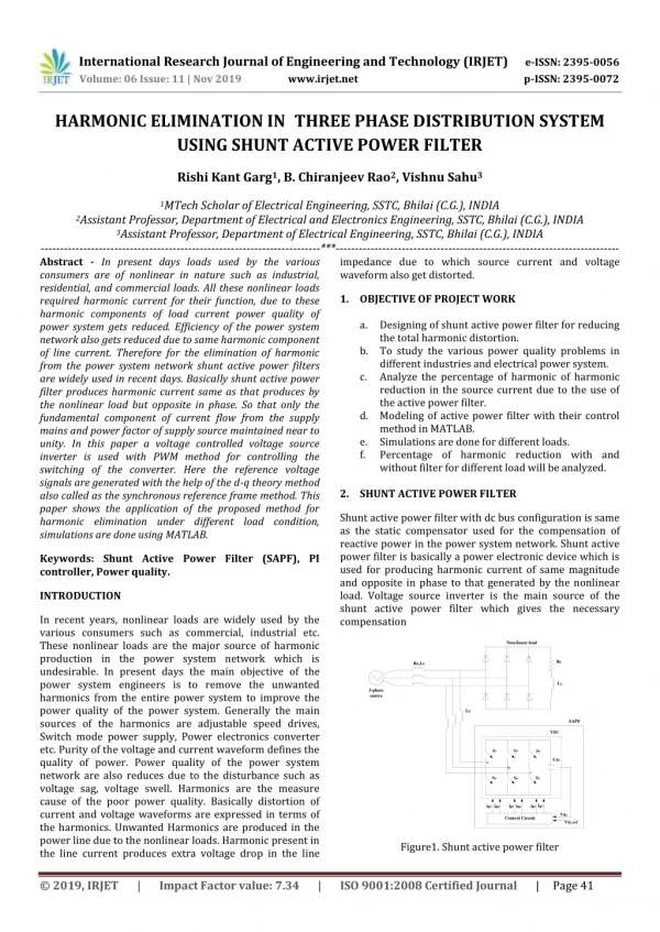
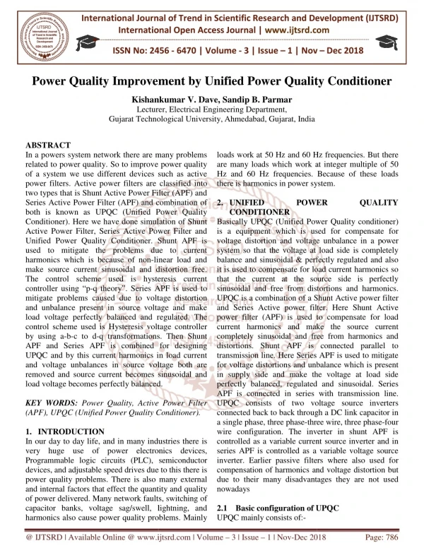
International Journal of Trend in Scientific Research and Development (IJTSRD) Volume 4 Issue 3, April 2020 Available Online: www.ijtsrd.com e-ISSN: 2456 – 6470 Power Quality Improvement using Shunt Active Power Filter Ankita Upadhyay1, Padmesh Singh2 1Scholar (PS&C), 2Associate Professor, 1,2Department of Electrical Engineering, Babu Banarasi Das University, Lucknow, Uttar Pradesh, India ABSTRACT Nowadays, usage of non-linear loads in power system is increasing. For example, UPS, inverters, converters, etc. These loads make the supply current non sinusoidal and distorted form, which is called harmonics. At this time Active power filters have been developed to improve power quality. In this Paper, a Shunt Active Power Filter (SAPF) control scheme has proposed to eliminate the current harmonics and improve the power quality. The shunt active power filter controlled by using the different controllers such as (PI, PID, Fuzzy logic, Pq Theory and hysteresis controller). In our proposed system, PI controller is used to reduce the harmonics current using the shunt active power filter. And both current THD results are compared, with and without use of filter and then shown how filters can reduce THD and is most suitable to control the shunt active power filter in term of total harmonic reduction(THD). MATLAB/SIMULINK power system toolbox is used to simulate the proposed system. KEYWORDS: Power Quality, Shunt Active Power Filter (SAPF), Hysteresis Current Controller, Harmonics, MATLAB/ Simulink How to cite this paper: Ankita Upadhyay | Padmesh Singh Improvement using Shunt Active Power Filter" Published in International Journal of Trend in Scientific Research and Development (ijtsrd), ISSN: 2456- 6470, Volume-4 | Issue-3, April 2020, pp.445-449, www.ijtsrd.com/papers/ijtsrd30463.pdf Copyright © 2020 by author(s) and International Journal of Trend in Scientific Research and Development Journal. This is an Open Access article distributed under the terms of the Creative Commons Attribution License (CC (http://creativecommons.org/licenses/by /4.0) "Power Quality IJTSRD30463 URL: BY 4.0) I. Nowadays, non linear loads in the distribution system generate power quality issue for power engineers. The utilization of power electronics device at the end consumer side is growing enormously because of the advancement in the semiconductor technology. The use of power electronics devices gives rise to problems like reactive power disturbance, disturbance to other consumer, harmonic generation, poor power factor, low system efficiency, heating of devices, etc. This adverse may becomes extensive in future year, hence it is very significant mitigate this problems. Mainly there are two approaches for the mitigation of power quality problems. The primary approach is load conditioning, which guarantee that the load is resistant harmonics. Equipments are made less responsive to power disturbance and harmonics, which is not so likely practically. The other solution is power line conditioning. In this approach line conditioning system is installed at point of common coupling (PCC) that counteracts or suppresses for the adverse consequence created by non linear harmonic creating loads. Conventionally passive filters were used to deal with reactive power disturbance problems and harmonic production. But they were facing major drawbacks like resonance problem, fixed compensation characteristics, large size, effect of source impedance on performance etc. so this result became less attractive. INTRODUCTION The concept of active power filter was introduced by Machida and Sasaki in 1971. Active power filters gives efficient result when compared to conventional passive filters for the mitigation of harmonic and reactive power disturbance problems. II. SHUNT ACTIVE POWER FILTERS It compensates the load current by injecting equal but opposite harmonic compensating current. It offers a low impedance path to harmonic currents at its tuned frequency. It acts as the current source that supplies the compensating current that the load needs and has a phase shift of 180 degree. An active Power filter satisfies the drawbacks of the Passive filters. Active power filters classified into two types. They are Shunt active power filter and Series active power filter. These paper discuss about to remove the current harmonics, so we consider only Shunt active filters. It is made up of MOSFET, IGBT, and GTO-Transistors etc. Fig. 1 shows the basic scheme of shunt active power filter which compensate load current harmonics by injecting equal but opposite harmonic compensating current. Fig. 1 shows the basic scheme of shunt active power filter which compensate load current harmonics by injecting equal but opposite harmonic compensating current. @ IJTSRD | Unique Paper ID – IJTSRD30463 | Volume – 4 | Issue – 3 | March-April 2020 Page 445
International Journal of Trend in Scientific Research and Development (IJTSRD) @ www.ijtsrd.com eISSN: 2456-6470 Fig1: Basic scheme of shunt active power filter Mostly shunt active power filter operates as a current source injecting the harmonic components generated by the load but phase shifted by 180°. Basically shunt active power filter are more efficient and less cost when compared to series active power filters since most of the non linear loads generate current harmonics. In addition series active power filter needs sufficient protection scheme. The combined shunt and series active filter is known as Unified Power Quality Conditioner (UPQC). III. PI CONTROLLER MODEL TECHNIQUE A.Basic controller simulink model of controller without filter B.Basic controller simulink model of controller with filter We run this model in Simulink and see the results of the measurement devices in graphical form and measure the THD of the three phase currents separately. All the graphs are shown below and THD of each phase is tabulated. In this paper we have analyzed the three phase four wire distribution system and point out the problems associated due to use of unbalanced non- linear loads. By the use of SAPF we have reduced current harmonics of the system which is shown in table. It also improves power factor and reduces neutral current which make system stable. The simulation results confirm the improvement of the quality of energy, by maintaining the THD of the source current after compensation well below5%, the harmonics limit imposed by the IEEE-519 standard. Fig 2 shows current waveform without filter. Three phase Current Waveform without SAPF 10 5 C u rre n t (a m p ) 0 -5 -10 1000 2000 3000 4000 5000 Time (sec) 6000 7000 8000 9000 Fig.2: Current waveform without filter @ IJTSRD | Unique Paper ID – IJTSRD30463 | Volume – 4 | Issue – 3 | March-April 2020 Page 446
International Journal of Trend in Scientific Research and Development (IJTSRD) @ www.ijtsrd.com eISSN: 2456-6470 Fig. 3 Parameter of Analysed system Symbol Quantity Vg Supply voltage F Grid frequency LL Line Inductance KP Proportional Gain KI Integral Gain Lsh Coupling Inductance Cdc APF DC Capacitor Vdc DC link Capacitor Voltage Value 100V(r.m.s.) 50 Hz 4.66mH 1.9 7.5 1.5mH 1100e-6F 283V @ IJTSRD | Unique Paper ID – IJTSRD30463 | Volume – 4 | Issue – 3 | March-April 2020 Page 447
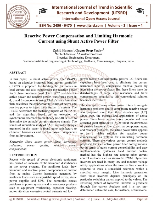
International Journal of Trend in Scientific Research and Development (IJTSRD) @ www.ijtsrd.com eISSN: 2456-6470 Current waveform using SAPF C.Phase c 40 30 20 10 C u rre n t (a m p ) 0 -10 -20 -30 -40 -50 0.7 0.8 0.9 1 1.1 1.2 1.3 1.4 1.5 1.6 4 Time (sec) x 10 Fig: 4 Current waveform with SAPF SIMULATION RESULTS In this paper, the simulation model of proposed shunt active power filter is shown in below figures. The simulation model is done by using MATLAB / SIMULINK. The analyses of current harmonic and power quality improvement for proposed Simulink are given below. THD Graphs of all phases without filter A.Phase a THD Graphs of all phases with filter A.Phase a IV. B.Phase b B.Phase b @ IJTSRD | Unique Paper ID – IJTSRD30463 | Volume – 4 | Issue – 3 | March-April 2020 Page 448
International Journal of Trend in Scientific Research and Development (IJTSRD) @ www.ijtsrd.com eISSN: 2456-6470 C.Phase c REFERENCES [1]Qian Liu, Li Peng, Yong Kang, Shiying Tang, Deliang Wu, and Yu Qi “A Novel Design and Optimization Method of anLCL Filter for a Shunt Active Power Filter” IEEE Transactions on industrial electronics, vol. 61, No. 8, pp:4000-4010,august 2014. [2]Anand Singh, Dr. Prashant Baredar, “Power Quality Analysis of Shunt Active Power Filter Based On Renewable Energy Source” IEEE International Conference on Advances in Engineering & Technology Research (ICAETR - 2014). [3]Jeevananthan. K. S, “Designing of Single Phase Shunt Active Filter Using Instantaneous Power Theory” International journel on Electric Engineering & Research, Vol. 2, Issue 2, pp: (1-10), Month: April - June 2014. [4]Quoc-Nam Trinh and Hong-Hee Lee, Senior Member, IEEE “An Advanced Current Control Strategy for Three- Phase Shunt Active Power Filters” IEEE Transactions on industrial electronics, vol. 60, no. 12,pp:5400-5411 December 2013. Fig. 5 Current THD Comparison [5]H. Sasaki and T. Machida, "A New Method to Eliminate AC Harmonic by Magnetic Compensation Consideration on Basic Design," IEEE Trans. on Power Apparatus and Syst., vol. 90, no. 5, pp. 2009-2019. S. No. 1. 2. 3. THD without SAPF 20.27% 20.22% 14.18% Reduced THD with SAPF 4.49% 4.67% 4.33% THD Phase a Phase b Phase c [6]H. Akagi, Y. Kanazawa, K. Fujita And A. Nabae “Generalized Theory of Instantaneous Reactive Power and Its Application” Electrical Engineering in Japan, Vol. 103, No. 4 , 1983 V. The shunt active power filter performance was analyzed by using the controller with PI reference current generator. The non-sinusoidal source current waveform is converted into sinusoidal current waveform even though the non-linear load is connected in the end-user of the power distribution system. The current harmonics waveform are reducing by injecting the opposite angle current waveform on the source side, using the shunt active power filter controlled by a hysteresis controller and improved the quality of power by more level of reducing the harmonics. Finally shows the result of the source side voltage and current waveform without the shunt active power filter and with shunt active power filter. This model developed by using the Matlab/Simulink. CONCLUSION [7]H. Akagi “Control Strategy and Site Selection of a Shunt Active Filter for Damping of Harmonic propagation in Power Distribution Systems” IEEE Transactions on Power Delivery, Vol. 12, No 1, 1997 [8]8. T. Narongrit, K-L. Areerak and K-N. Areerak “The Comparison Study of Current Control Techniques for Active Power Filters” 2011 9. H. Akagi “New Trends in Active Filter for Power Conditioing” IEEE Transactions on Industry Applications, Vol 32, No 6, 1996 10. H. Akagi, E. H. Watanabe, M. Aredes “Instantaneous Power Theory and Application to Power Conditioning” IEEE Press, 2007. @ IJTSRD | Unique Paper ID – IJTSRD30463 | Volume – 4 | Issue – 3 | March-April 2020 Page 449