Download
1 / 34
350 likes | 396 Views
Learn the advantages of installing shunt-capacitor banks for improved power factor, reduced losses, and enhanced electrical system performance in industrial plants. Understand the importance of selecting the correct capacitor size and managing transient inrush currents to prevent overvoltage issues. Discover methods to limit inrush currents and ensure efficient capacitor switching.

E N D
Shunt Capacitor Switching ForPower Factor Improvement Clayton H Reid
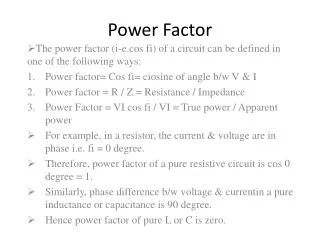
Power Factor Kw is productive power Kvar is non productive
Industrial Plant Electrical Load • Induction Motors • Induction Furnaces • Fluorescent Lighting
Advantages of Installing Capacitors • Improved Power Factor • Released System Capacity • Improved Motor and Lighting Performance • Reduced Current and Losses • Decreased Transformer Losses
Shunt-capacitor Banks • Automatic switching of capacitor banks • Voltage Control-a voltage sensitive relay is used which responds to changes in line voltage • Current Control-a current sensitive relay is used which responds to changes in line current • Kilovar Control-a kilovar relay is used which responds to changes in reactive loads
Capacitors Switched with Motor • Another means of obtaining automatic switching is to connect the capacitor to the motor and switch the motor and capacitor as a single unit
Capacitors Switched with Motor • The importance of selecting the correct size of capacitor to be switched with a given motor load • Location of capacitor connected points • Capacitor switching for special motors and for special motor-starting applications
Capacitors Switched with Motor • Transient inrush current and frequency for the following cases: • When a single capacitor is energized on a system • When a capacitor is energized in parallel with capacitor banks already connected • Effect of transient currents on contactors • Use of air-core reactors to limit transient current in parallel switching of capacitors
Overvoltage Due To Excessive Capacitance • Capacitor connected to the motor and starter de-energized, motor acts as an induction generator with shunt capacitor excitation
Maximum Voltage Generated • Size of capacitor • Speed of motor • No load characteristics
Transient Frequency - transient frequency - power frequency
Capacitor Inrush Current Ca Ep 2 Ip = La Ip= peak in rush current in amps Ep= r.m.s phase voltages in volts Ca= total circuit capacitance in farads La= total circuit inductance in henries Between C1 and C2
Summary • Capacitor selection can be made from manufactures literature. Will provide correction to approx. 95% lagging, voltage will be limited to 110% when motor disconnected. • Capacitors should be connected ahead of overload relays. If connected after the relays Overload section should be selected based on reduced current through the relays. • Do not connect capacitors to the winding of a motor driving a high inertia load.as torque transients up to 20 times can occur resulting in mechanical damage to motor shaft and driven machinery
Summary • To avoid torque transient problems for motor and driven machinery,capacitors should not be connected directly to the motor in the following : • a) any open transition reduced voltage starter • b) reversing starters, or starters which are used for for jogging the motor • c) two speed motors • d) wye-delta motors • Use a separate contactor to switch the capacitor
Summary • When capacitors are installed in motor control centers additional inductance should be installed in series with the capacitors to limit transient charging current.This will reduce contact erosion in the contactor