Download
1 / 6
60 likes | 80 Views
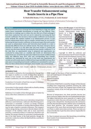
The Conventional sources of energy have been depleting at a high rate, which makes future sustainable development of energy use very difficult. Thus, researches on seeking ways to reduce the size and cost of heat exchangers have been conducted. Size and cost can be reduced by increasing the heat transfer coefficient. The increase in heat transfer coefficient can be done by many methods the common method is by Enhancement process. In this process enhancement device such as nozzles, twisted tapes etc are used for enhancing the heat transfer coefficient. In the present paper the work nozzles are used as enhancement device and Convective heat transfer in a tube is dynamically different from one without inserts. The main concept is due to insertion of nozzles in to the plain pipe and swirl motion is created and contact area decreases thereby increasing the heat transfer coefficient 'h', in the tube flow, an experimental setup is prepared and experiments are conducted by using water as a medium and results are determined. The experiments are carried for the plain pipe without any inserts at different heat input and different mass flow rates and corresponding heat transfer coefficient are calculated for each case, in the same way experiments are carried out with nozzle inserts at different heat input and different mass flow rates and corresponding heat transfer coefficient are calculated for each case. Thus, by these enhancement techniques, heat transfer rate is determined. R. Rudrabhi Ramu | P. H. J. Venkatesh | K. Leela Kumar "Heat Transfer Enhancement using Nozzle Inserts in a Pipe Flow" Published in International Journal of Trend in Scientific Research and Development (ijtsrd), ISSN: 2456-6470, Volume-4 | Issue-4 , June 2020, URL: https://www.ijtsrd.com/papers/ijtsrd31002.pdf Paper Url :https://www.ijtsrd.com/engineering/mechanical-engineering/31002/heat-transfer-enhancement-using-nozzle-inserts-in-a-pipe-flow/r-rudrabhi-ramu<br>

E N D
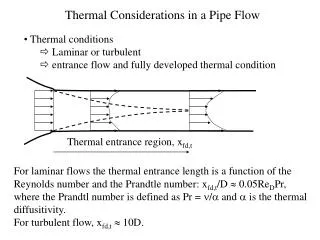
International Journal of Trend in Scientific Research and Development (IJTSRD) Volume 4 Issue 4, June 2020 Available Online: www.ijtsrd.com e-ISSN: 2456 – 6470 Heat Transfer Enhancement using Nozzle Inserts in a Pipe Flow R. Rudrabhi Ramu, P. H. J. Venkatesh, K. Leela Kumar Department of Mechanical Engineering, Vignans Institute of Information Technology (A), Visakhapatnam, Andhra Pradesh, India ABSTRACT The Conventional sources of energy have been depleting at a high rate, which makes future sustainable development of energy use very difficult. Thus, researches on seeking ways to reduce the size and cost of heat exchangers have been conducted. Size and cost can be reduced by increasing the heat transfer coefficient. The increase in heat transfer coefficient can be done by many methods the common method is by Enhancement process. In this process enhancement device such as nozzles, twisted tapes etc are used for enhancing the heat transfer coefficient. In the present paper the work nozzles are used as enhancement device and Convective heat transfer in a tube is dynamically different from one without inserts. The main concept is due to insertion of nozzles in to the plain pipe and swirl motion is created and contact area decreases thereby increasing the heat transfer coefficient ‘h’, in the tube flow, an experimental setup is prepared and experiments are conducted by using water as a medium and results are determined. The experiments are carried for the plain pipe without any inserts at different heat input and different mass flow rates and corresponding heat transfer coefficient are calculated for each case, in the same way experiments are carried out with nozzle inserts at different heat input and different mass flow rates and corresponding heat transfer coefficient are calculated for each case. Thus, by these enhancement techniques, heat transfer rate is determined. KEYWORDS: Energy; heat transfer coefficient; Enhancement process; swirl motion INTRODUCTION Heat transfer is defined as the transmission of energy from one region to another as a result of temperature gradient. Modes of heat transfer are mainly three modes of heat transfer Conduction, Convection and Radiation. Conduction: It is transfer of heat from one part of substance to another part of same substance. Convection: It is the transfer of heat with in a fluid by mixing of one portion of fluid with another. Radiation: It is transfer of heat through space or matter by means other than conduction or convection. Convection Heat transfer by convection occurs only when a temperature difference exists between a solid and a fluid flowing past it. Convection is essentially a process of energy transport affected by the circulation or mixing of fluid medium which may be a gas, a liquid or a powdery substance. The transport of heat energy during convection is directly linked with the transport of the medium itself, and as such convection presents a combined problem of conduction, fluid flow and mixing. The energy transfer in convection is predominantly due to the bulk motion of the fluid particles, though the molecular conduction within the fluid itself also contributes to some extent. How to cite this paper: R. Rudrabhi Ramu | P. H. J. Venkatesh | K. Leela Kumar "Heat Transfer Enhancement using Nozzle Inserts in a Pipe Flow" Published in International Journal of Trend in Scientific Research and Development (ijtsrd), ISSN: 2456- 6470, Volume-4 | Issue-4, June 2020, pp.388-393, URL: www.ijtsrd.com/papers/ijtsrd31002.pdf Copyright © 2020 by author(s) and International Journal of Trend in Scientific Research and Development Journal. This is an Open Access article distributed under the terms of the Creative Commons Attribution License (CC (http://creativecommons.org/licenses/by /4.0) IJTSRD31002 BY 4.0) With respect to the cause of fluid circulation of flow, two types of convection are distinguished: Free convection Forced convection Free convection Circulation of bulk fluid is caused by changes in fluid density resulting from temperature gradients between the solid surface and mass of fluid. The stagnant layer of fluid in the immediate vicinity of the hot body gets thermal energy by conduction. Because of temperature rise, these particles become less dense and hence lighter than the surrounding fluid particles. The lighter fluid particles move upwards to a region of low temperature where they mix with and transfer a part oftheir energy to the cold particles. Simultaneously, the cool heavier particles descend downwards to fill the space vacated by the warm fluid particles. The circulation pattern, upward movement of the warm fluid and downward movement of cool fluid, is called convection currents. These currents are setup naturally due to gravity alone and are responsible for free convection. Ex: Heat treatment processes like Quenching, normalizing, Heat transfer from transmission lines etc. Forced convection @ IJTSRD | Unique Paper ID – IJTSRD31002 | Volume – 4 | Issue – 4 | May-June 2020 Page 388
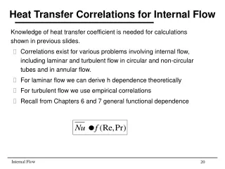
International Journal of Trend in Scientific Research and Development (IJTSRD) @ www.ijtsrd.com eISSN: 2456-6470 If the fluid motion is principally produced by some superimposed velocity field (like a fan, blower of a pump), the energy transport is said to be due to forced convection. The convection heat is affected to an appreciable extent by the nature of fluid flow. Ex: Cooling of I.C. engine cylinder, Refrigerating coils etc In the realms of fluid mechanics, essentially two types of fluid flow are characterized: Laminar flow and Turbulent flow Laminar flow The fluid particles move in flat or curved un-mixing layers of streams and follow a smooth continuous path. The paths of fluid movement are well- defined and the fluid particles retain their relative positions at successive cross-sections of the flow passage. There is no transverse displacement of fluid particles; the particles remain in an orderly sequence in each layer. Turbulent flow The motion of fluid particles is irregular, and it proceeds along erratic and unpredictable paths. The stream lines are intertwined and they change in position from instant to instant. Fluctuating transverse velocity superimposed on the main flow, and the velocity of individual fluid elements fluctuate both along the direction of flow and perpendicular to it. The rate of heat transfer by convection is mainly governed by Newton's law of cooling. Newton's law of cooling This law states that the heat transfer rate is directly proportional to surface area exposed to the heat transfer and temperature difference of the solid and undisturbed temperature of fluid. The heat transfer rate is given by the equation: Q= h×A×(Ts-Ta) Where, Q is Heat input,h is Convective heat transfer coefficient, A is Lateral surface area of the pipe,Ts is Surface temperature of the solid,Ta is ambient temperature of the fluid Heat transfer enhancement: Energy and the material saving considerations as well as space constraints have prompted an expansion of the efforts aimed at producing more efficient heat exchange equipment though the enhancement applications are numerous. Enhancement techniques, where inserts are used in the flow passage are advantages because the insert manufacturing process is simple and these technique can be easily employed. Twisted tapes, wire coils, ribs, fins, dimples, etc, are the most commonly used heat transfer enhancement tools. These are known to be economic heat transfer enhancement tools. The former insert is found to be suitable in a laminar flow regime and the latter suitable for turbulent flow. The thermo hydraulic behavior of an insert mainly depends on the flow conditions (laminar of turbulent) apart from the insert configurations. Applications: Enhancement methods are widely employed in the enhancement of heat transfer rates in various industrial processes. Figure1. Concentric tube heat exchanger In Increasing the rate of heat transfer in a concentric tube heat exchanger by inserting conical nozzles: In enhancing heat transfer rate in micro channel and mini channel flows by single phase enhancement methods. In geothermal and ocean thermal power plants the enhanced heat transfer techniques are widely employed to minimize the performance. Enhancement methods are widely used in improvement of shell and tube heat exchangers, in fouling control, in gas turbine heat transfer and in similar applications. Enhancement techniques: Heat transfer techniques are commonly used in areas such as process industries, heating and cooling in evaporators, thermal power plants, air-conditioning equipment, refrigerators, radiators for space vehicles, automobiles, etc Roughned surface: Surface roughness can be produced by the machining of the surface as well as by casting, forming and welding processes. Clearly, an infinite number of geometric configurations possible, each having its own heat transfer and pressure drop characters tics. Experimental techniques generally are used to determine the heat transfer coefficient and friction factor for flow, since no unified analysis in available for predicting them by purely theoretical means. components are The artificial surface roughness was fabricated in parallel and essentially in the orthogonal direction to the mean flow, a much greater enhanced forced convection was obtained by cutting v-grooves or fixing square ribs at uniform spacing, rather than fabricating random roughness on the internal surfaces by machining processes, on addition, the best thermal performance was achieved with the ribbed surface. Extenended surfaces: The use of fins on the outer surface of tubes to enhance heat transfer is well known. Internally finned tubes have been used also to enhance heat transfer to fluids flowing inside tubes. Heat transfer and friction factor correlations have been presented for internally finned tubes under laminar and turbulent flow conditions. @ IJTSRD | Unique Paper ID – IJTSRD31002 | Volume – 4 | Issue – 4 | May-June 2020 Page 389
International Journal of Trend in Scientific Research and Development (IJTSRD) @ www.ijtsrd.com eISSN: 2456-6470 thermocouple probes. Then to the pipe of length 450mm flanges are fitted on both the sides.Then, 4 Heater coils are wounded on the pipe and there after asbestos rope is wounded on the heater coils to resist the heat to flow outside. Then pipe section is fitted to the table by using flange and bolts. The inlet and outlet pipes are fitted as shown in the figure3 Preparation of table: Materials required Ply wood sheet of 8×6 sqft. 1.Sanmica sheet of 8×6 sqft. 2.4 GI rods of diameter 45mm and of length 560mm. 3.4 L-Clamps 2 clamps of length 1200mm 4.2 clamps of length 560mm Procedure: Preparation of base: Plywood sheet of length 1200*560 mm² is been cut by using power hacksaw and sanmica sheet of same length and breadth as mentioned above has been pasted by using SR solution. Preparation of box: Plywood sheet of length 1200×560 mm² and height 56cm has been cut and sanmica of same length, breadth and height is pasted on it. Main purpose of this box is to fix various accessories needed. Various slots are drilled by using hand drilling machine to fix various parts like ammeter, voltmeter, dimmer stat, power supply unit, selector switch, temperature indicator etc. Figure2. Roughened Surface Figure3. Nozzle Optimization methods: The increasing heat transfer with enhancement is accompanied by an increase in the friction factor. In some situations the heat transfer coefficients are increased in most about 4times while the friction factors are increased as much as 50% of more. An increased friction factor implies an increased power for pumping the fluid. So the results of enhancement, when it is applied to produce more efficient heat exchange equipment, should be weighed against the increased power requirement for pumping fluid.For a given enhancement technique, if the heat transfer and the friction factor data are available as a function of the Reynolds number, it may be possible to optimize the system to reduce the heat transfer surface, to obtain increased heat transfer capacity, are to reduce the power required for pumping the fluid. PREPARATION OF EXPERIMENTAL SETUP There are mainly two stages: Stage 1: Preparation of test section Stage 2: Preparation of table Preparation of test section: Materials required 1.3 GI pipes of 45mm diameter Two pipes of length 450mm One pipe of length 120mm 2.Asbestos rope of 8mm thickness. 3.4 heater coils of 800watts capacity. 4.5 MS type flanges of diameter 40mm. 5.2 Elbows of 40mm diameter. 6.2 Nipples of 40mm diameter. 7.One gate valve of 45mm diameter. 8.2 reduced sockets. Procedure: At first the pipe is cleaned by using emery paper and then copper tubes of equal length are gas welded for fitting the Figure3. Experimental Setup Preparations of conical nozzle inserts: Machined from solid bar on lathe up to 40mm outer diameter and a length of 50mm is made to cut. A bore of 20mm diameter is made with boring tool bit. By rotating the tool post to angle (120), the internal taper is made with 39mm and 20mm end diameters. Table 1.Preparations of conical nozzle inserts S no Sequence of operation 1 Facing operation 2 Planning 3 Taper turning 4 Finishing Experimentation: At load of 75w Machine Lathe machine Lathe machine Lathe machine Grinding machine @ IJTSRD | Unique Paper ID – IJTSRD31002 | Volume – 4 | Issue – 4 | May-June 2020 Page 390
International Journal of Trend in Scientific Research and Development (IJTSRD) @ www.ijtsrd.com eISSN: 2456-6470 Table 2.The steady state readings of plain tube (A) T1 ˚c T2 ˚c T3 ˚c T4 ˚c T5 ˚c T6 ˚c hw/m²k 0.5 32 37 36 39 0.5 32 38 37 39 0.5 31 39 37 39 0.5 29 39 36 37 0.5 33 40 39 41 0.5 33 40 39 41 Table3. Steady state readings for 2- aluminum nozzles inserts (V) (A) T1 ˚c T2 ˚c T3 ˚c T4 ˚c T5 ˚c T6 ˚c hw/m²k 150 0.5 33 40 38 150 0.5 33 39 38 150 0.5 33 39 38 150 0.5 33 40 39 150 0.5 34 42 40 150 0.5 34 40 40 S no 1 2 3 4 5 6 (V) 150 150 150 150 150 150 Re 1221 1240 1225 1200 1273 1281 36 37 36 36 38 38 34 35 34 34 36 36 294.8 277.4 224.6 214.4 235.8 235.8 S no 1 2 3 4 5 6 Re 1138 1131 1152 1138 1174 1167 41 41 40 40 42 42 38 38 38 38 39 39 36 36 36 36 37 37 248.2 262.0 277.4 248.2 224.6 248.2 Table4. Steady state readings for 3- aluminum nozzles inserts S no Voltage (V) Current (A) T1 ˚c T2 ˚c T3 ˚c T4 ˚c T5 ˚c T6 ˚c H w/m²k 1 150 0.5 32 33 2 150 0.5 34 42 3 150 0.5 34 44 4 150 0.5 34 44 5 150 0.5 34 44 Re 839.4 971.7 949.6 971.7 971.7 35 41 42 42 42 38 45 44 44 44 38 40 41 40 40 34 39 39 38 38 393.08 214.40 188.6 181.4 181.4 Similarly for all other nozzles the readings are taken and tabulated for calculations. At the load of 200w Table 5. Steady state value readings for plain tube S no (V) (A) T1 (°c) T2 (°c) T3 (°c) T4 (°c) T5 (°c) T6 (°c) H W/m2k 1 200 1 34 46 2 200 1 34 43 3 200 1 34 47 4 200 1 34 45 5 200 1 33 45 6 200 1 33 47 7 200 1 33 47 Table 6. Steady state readings for 2- aluminum nozzles inserts S no Voltage (V) Current (A) T1 (°c) T2 (°c) T3 (°c) T4 (°c) T5 (°c) T6 (°c) H W/m2k 1 200 1 35 42 2 200 1 36 45 3 200 1 36 43 4 200 1 36 43 5 200 1 33 44 Similarly all other readings are taken for calculation. MODEL CACULATIONS Table7. Steady state value with 2 nozzle inserts at load of 75w S no (V) (A) T1 ˚c T2 ˚c T3 ˚c T4 ˚c T5 ˚c T6 ˚c H w/m²k 1 150 0.5 34 38 Re 990.8 993.8 996.9 1018.8 977.3 983.3 983.0 42 44 44 44 43 43 43 46 46 47 46 46 46 46 41 42 41 41 41 41 41 39 40 39 39 38 38 38 477.1 512.4 477.1 461.2 419.2 395.6 359.3 Re 981.1 1023.9 1004.6 996.4 989.01 40 46 41 41 44 41 42 42 42 42 38 40 39 39 41 37 37 38 37 37 739.9 465.8 838.5 662.0 405.2 Re 899.4 37 38 36 35 428.8 Table8. Steady state value with 2 nozzle inserts at load of 200w (V) (A) T1 ˚c T2 ˚c T3 ˚c T4 ˚c T5 ˚c T6 ˚c H w/m²k 200 1 33 44 44 S no 1 Re 989. 42 41 37 405 We know, Q= h×A×(Ts-Ta) Now, Ts= (T2+T3+T4+T5)/4 = (38+37+38+36)/4= 37.25 ˚c. Ta= (T1+T6)/2 = (34+35)/2 = 34.5 ˚c A= lateral surface area of pipe = Π×D×L = Π×0.045×0.45= 0.0636m² @ IJTSRD | Unique Paper ID – IJTSRD31002 | Volume – 4 | Issue – 4 | May-June 2020 Page 391
International Journal of Trend in Scientific Research and Development (IJTSRD) @ www.ijtsrd.com eISSN: 2456-6470 Therefore, h= Q/ (A×(Ts-Ta) = (150×0.5)/ (0.0636×(37.25-34.5) h= 428.8 w/m²k Calculation of Reynolds number: We know, Re= (V×D)/ (٧) ٧ = value of kinematic viscosity at bulk temperature from data book.V= velocity = Q/A, Q is discharge which is calculated by noting down time taken for filling the measuring jar of capacity 1Lit Q=2.43×10⁻⁵ A= (Π×D²)/4= (Π×0.045²)/4 = 0.00158m² Now, V= (2.43×10⁻⁵)/(0.00158) = 0.015m/sec. Bulk temperature = (Ts+Ta)/2 = (37.52+34.5)/2 = 34.5 ˚c Value of Ѵ from data book at 34.5 ˚c is 0.7505×10⁻⁶ Re = (0.015×0.045)/ (0.6634×10⁻⁶) = 899.4 Calculation for steady state value with 2 nozzle inserts at load of 200w We know, Q= h×A×Ts-Ta) Now, Ts= (T2+T3+T4+T5)/4 = (44+44+42+41)/4= 42.75 ˚c. Ta= (T1+T6)/2 = (33+37)/2 = 35 ˚c A= lateral surface area of pipe = Π×D×L = Π×0.045×0.45= 0.0636m² Therefore, h= Q/ (A×(Ts-Ta) = (200×1)/ (0.0636×(42.75-35) h= 405.2w/m²k Calculation of Reynolds number: We know, Re= (V×D)/ (٧) ٧ = value of kinematic viscosity at bulk temperature from data book. Bulk temperature = Average of surface and ambient temperature V= velocity = Q/A Q is discharge which is calculated by noting down time taken for filling the measuring jar of capacity 1lt. Q=2.43×10⁻⁵ A= (Π×D²)/4= (Π×0.045²)/4 = 0.00158m² Now, V= (2.43×10⁻⁵)/ (0.00158) = 0.015m3/sec. Bulk temperature = (Ts+Ta)/2 = (42.75+35)/2 = 38.5 ˚c Value of Ѵ from data book at 38.5 ˚c is 0.6825×10⁻⁶ Re = (0.015×0.045)/ (0.6825×10⁻⁶) = 989.01 The values of bulk mean temperature, Reynolds number, heat transfer coefficient which are obtained during the experiments are tabulated below RESULTS Table 9.At 75 W Heat transfer Coefficient No of nozzle inserts Bulk mean temperature( ˚c) Reynolds number Heat transfer coefficient (w/m²k) 0 39.25 2 37.85 3 37.00 4 36.75 5 36.50 6 34.50 Table10.At 200 W Heat transfer Coefficient No of nozzle insertsBulk mean temperature ˚cReynolds numberHeat transfer coefficient (w/m²k) 2 38.50 3 38.60 4 37.62 5 38.00 6 39.37 971.7 989.2 1010.8 1068.4 1167.1 1281.4 181.4 235.8 248.2 262.0 294.8 428.8 989.01 1057.5 1097.5 1170.6 1360.9 405.2 433.7 503.1 524.1 546.8 @ IJTSRD | Unique Paper ID – IJTSRD31002 | Volume – 4 | Issue – 4 | May-June 2020 Page 392
International Journal of Trend in Scientific Research and Development (IJTSRD) @ www.ijtsrd.com eISSN: 2456-6470 Graphs CONCLUSION The Experimental investigation for using conical nozzle inserts shows that the heat transfer in the circular tube could be enhanced by inserting conical nozzles inserts at different loads the heat transfer coefficient increases and Reynolds number decreases gradually. There is 62.5% increase in heat transfer coefficient when a load of 75w is applied. There is 52.1% increase of heat transfer coefficient when a load of 200w is applied. Due to increase in heat transfer coefficient there is increase in friction factor. So, it is advantageous to use where friction factor is not considered. In the present paper, the experiments are conducted for the enhancement of heat transfer for the tube flow with water. The experiments can be extended to study the pressure drop due to inserts. Enhancement of heat transfer can also be carried out in laminar flow region. Enhancement methods like insertion of tapes, wire coils prove to be efficiently increasing the performance characteristics and are economical in the usage. So, these are widely employed in the industrial applications and they are going to be one of the preferred methods for the enhancement of heat transfer in various fields, in the future. REFERENCES [1]R. C. Sachdeva. “Fundamentals of engineering heat and mass transfer”, new age publications. 500 450 400 350 300 250 200 150 100 50 Figure 4.Graph between Re on X-axis and h on Y-axis at load of 75w 900 [2]J. P. Holman, “Heat and mass transfer”, Tata mcgraw hill 800 700 [3]R. K. Rajput, Heat transfer, S. chand publications [4]C. P. kothandaramam, S. Subramanyam, “Heat and mass transfer Data book”, New Age international publications. 600 500 [5]Heat transfer enhancement in self-sustained oscillatory flow in a grooved channel with oblique plates byAbdelkaderKorichia,Volume 6, February 2009, Pages 1138-1148 400 52, Issues 5– 300 [6]Development characteristics of laminar flow in a tube fitted with regularly spaced twisted-tape elements by A. W. Date and U. N. Gaitonde Volume 3, Issue 4, July 1990, Pages 373-382 of correlations for predicting 200 100 Figure 5.Graph between Re on X-axis and h on Y-axis at load of 200W @ IJTSRD | Unique Paper ID – IJTSRD31002 | Volume – 4 | Issue – 4 | May-June 2020 Page 393