Download
1 / 4
50 likes | 132 Views
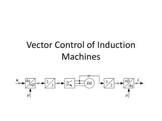
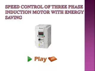
In the Vector Control method of induction motors, one of the advantages of the separately excited DC motor of being able to decouple the flux control and the torque is thereby opened up. The field orientation control of induction motor allows decoupling the control of magnetic flux and the control of the torque produced by the stator current. To drive three phase squirrel cage induction motor with a constant speed, vector control technique is used. In this paper, the development of speed control system for three phase squirrel cage induction motor using a vector control method is presented and simulation for proposed system is done with the help of MATLAB SIMULINK. Soe Sandar Aung | Thet Naing Htun "Speed Control System of Induction Motor by using Vector Control Method" Published in International Journal of Trend in Scientific Research and Development (ijtsrd), ISSN: 2456-6470, Volume-3 | Issue-5 , August 2019, URL: https://www.ijtsrd.com/papers/ijtsrd27914.pdf Paper URL: https://www.ijtsrd.com/engineering/electrical-engineering/27914/speed-control-system-of-induction-motor-by-using-vector-control-method/soe-sandar-aung<br>

E N D
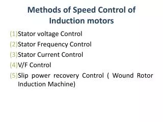
International Journal of Trend in Scientific Research and Development (IJTSRD) Volume 3 Issue 5, August 2019 Available Online: www.ijtsrd.com e-ISSN: 2456 – 6470 Speed Control System of Induction Motor by using Vector Control Method Soe Sandar Aung1, Thet Naing Htun2 1Professor, 2Associate Professor 1,2Department of Electrical Power Engineering, Mandalay Technological University, Mandalay, Myanmar How to cite this paper: Soe Sandar Aung | Thet Naing Htun "Speed Control System of Induction Motor by using Vector Control Method" Published in International Journal of Trend in Scientific Research and Development (ijtsrd), ISSN: 2456- 6470, Volume-3 | Issue-5, August 2019, https://doi.org/10.31142/ijtsrd27914 Copyright © 2019 by author(s) and International Journal of Trend in Scientific Research and Development Journal. This is an Open Access article distributed under the terms of the Creative Commons Attribution License (CC (http://creativecommons.org/licenses/by /4.0) The field orientation control of induction motor allows decoupling the control of magnetic flux and the control of the torque produced by the stator current. This makes the induction motor control more akin to the control of the separately excited DC motor. That is, in three phase induction motor control, the rotor field can be equivalent to the field of excitation of dc motor, but with the difference that the voltage in the rotor, which produces the field, is dependent on the magnetic field in the stator. II. Methods of Vector Control The way of determining the angle position of the rotor flux vector, rotating at the synchronous speed, depends on the type of the field orientation: either direct field orientation or indirect field orientation. A.Direct Field Orientation Method When the identification of the flux vector is done by direct Hall sensor measurement or even indirectly by estimation of other motor electrical variables, it is called direct field orientation. This method depends on measuring the air gap flux using special sensor is called Hall-Effect-Device. The magnetic flux measured is the mutual flux not the rotor flux, which Paper has Dangle- which is Important to be properly oriented. The connection with the known stator current provides the solution of determining this angle. Proportional Integral (PI) controller methodology is used in both the flux and the torque loops to get the desired direct and quadrature components of the stator current in the ABSTRACT In the Vector Control method of induction motors, one of the advantages of the separately excited DC motor of being able to decouple the flux control and the torque is thereby opened up. The field orientation control of induction motor allows decoupling the control of magnetic flux and the control of the torque produced by the stator current. To drive three-phase squirrel-cage induction motor with a constant speed, vector control technique is used. In this paper, the development of speed control system for three-phase squirrel-cage induction motor using a vector control method is presented and simulation for proposed system is done with the help of MATLAB/SIMULINK. KEYWORDS: Field orientation control, three-phase squirrel-cage induction motor, vector control method I. INTRODUCTION Induction motor plays a very important role in both worlds, because of low cost, reliable operation, robust operation and low maintenance. There are two main types of induction motors which are the wound rotor and squirrel-cage motor and both of them are in widespread use. Squirrel-cage rotor winding design is considered more reliable and cheaper to be made. Control of a three-phase squirrel cage induction motor is difficult, because it is not simply about independently controlling the voltage and the frequency only. But the vector control method can perform a faster critically damped response that is non- oscillating. IJTSRD27914 pp.2254-2257, BY 4.0) synchronous reference frame. Those are then transformed to the same component in the stationary frame. Finally the equations of control are referenced to the three phase motor drive currents to control the inverter operating conditions. B.Indirect Field Orientation Method For very low-speed operations and for position type control, the use of flux sensing that relies on integration which has a tendency to drift may not be acceptable. A commonly-used alternative is indirect field orientation, which does not rely on the measurement of the air gap flux, but uses the condition in Equations 1 to 3 to satisfy the condition for proper orientation The above conditions, if satisfied, ensure the decoupling of the rotor voltage equations. To what extent this decoupling is actually achieved will depend on the accuracy of motor parameters used. Since the values of rotor resistance and magnetizing inductance are known to vary somewhat more than the other parameters, on-line parameter adaptive techniques are often employed to tune the value of these @ IJTSRD | Unique Paper ID – IJTSRD27914 | Volume – 3 | Issue – 5 | July - August 2019 Page 2254
International Journal of Trend in Scientific Research and Development (IJTSRD) @ www.ijtsrd.com eISSN: 2456-6470 parameters used in and indirect field-oriented controller to ensure proper operation. Figure.3 Three-phase to d-q Stationary Reference Frame Transformation Figure.1 Indirect Field-oriented Control of Current- regulated PWM Inverter Induction Motor Drive III. There are three main references of motion, which could be used to model the three phase induction machine in its three main regions of operation. These are stationary reference frame for startup, the synchronous reference frame for equilibrium motion, and the rotor reference frame for changing speeds by acceleration or deceleration. The two commonly employed coordinate transformations with the induction machine are the stationary and the synchronous reference frame. These mathematical transformations, which are known as Park Transformation, can facilitate the understanding of the variation of mutual inductance between the stator and the rotor under differing rotation conditions. In this paper, the modeling is done in synchronous reference frame where the variables appear as DC quantities facilitating smooth control. Here, the three phase variables (a-b-c variables) are first transformed into stationary reference frame using Clark’s transformation and the d-q axis variables are obtained using Park’s transformation, there by facilitating controller design and evaluation of transient phenomena in the drive system. Figure 2 shows the equivalent circuit of d-q axes of induction motor. Mathematical Model of Induction Motor Figure.4 d-q Stationary Frame to d-q Synchronous Frame Transformation Where P is the number of pole and Te is the electromagnetic torque TL is load torque, J is the inertia of the rotor and connected load B is the friction. The Simulink block of electromagnetic torque is shown in Figure 5 and the Simulink block of motor speed is shown in Figure 6. Figure.2 Equivalent Circuit in d-q Axes of Induction Motor Figure.5 Simulink Blocks of Electromagnetic Torque Figure6. Simulink Blocks of Motor Speed @ IJTSRD | Unique Paper ID – IJTSRD27914 | Volume – 3 | Issue – 5 | July - August 2019 Page 2255
International Journal of Trend in Scientific Research and Development (IJTSRD) @ www.ijtsrd.com eISSN: 2456-6470 IV. Propose Control System of Induction Motor Using Vector Control Scheme V. The vector control drive for 11 kW three-phase squirrel-cage inductions motor is shown in figure 7. In this drive, the speed is set at 750 rpm and the flux reference is maintained at 0.8. At 0.6 sec the load torque change from no-load to 3.48 Nm, at 1.8 sec the load torque change from 3.49 Nm to 17.4 Nm, at 3 sec the load change from 17.4 Nm to 41.76 Nm, at 4.2 sec the load torque change from 41.76 Nm to 3.48 Nm and at 5.4 sec the load torque change from 3.48 Nm to 0. The resultant three-phase current of vector control of induction motor is shown in figure 10. The load is increased at 0.6 sec, 1.8 sec, 3 sec and decreased at 4.2 sec, 5.4 sec. In this case it seen that, when the load on the motor is increased the motor currents are increased and when the load on the motor is decreased the motor currents are decreased. At maximum load torque (41.76 Nm), the currents are reaching to 18 A. Result Figure.7 Overall Simulink Model of Vector Control for Induction Motor Figure8.Simulation Diagram for PWM Inverter Figure.10 Three-phase Currents Response of Vector Control Figure 11 shows the rotor speed of the machine at different load torque. This demonstrates that high dynamic performance speed response to change in demand torque. The sudden application of the load on the motor shaft cause a small dip or rise in the rotor speed, which recovers quickly resulting in zero steady state speed error. In figure 11, the speed reaching to the desired speed at 0.2 sec and is loaded 3.48 Nm, the speed decreases to the 745 rpm and return to the desired speed in 0.1 sec. When the load torque is changed from 3.8 Nm to 17.4 Nm, the speed decreases to the 710 rpm and return to the desired speed in 0.2 sec. When the load torque is changed from 17.4 Nm to 41.76 Nm, the speed decreases till 690 rpm and return to the desired speed in 0.3 sec. When the load torque is changed from 41.76 Nm to 3.48 Nm, the speed increases till 850 rpm and return to the desired speed in 0.3 sec. When the load torque is changed from 3.8 Nm to 0 for no load, the speed increases to the 755 rpm and return to the desired speed in 0.1 sec. It is seem that the speed responses were smooth at different load torques and the speed follow perfectly the speed reference. The speed response is fast, accurate and gives a good result for variable load torque of induction motor. Figure.9 Simulink Model of Vector Control Block The overall Simulink model of vector control system for induction motor is shown in figure 7. Figure 8 is PWM Inverter generation block and figure 9 is Vector Control Block. For the induction motor control, the modeling and simulation is carried out with MATLAB/ SIMULINK software. For the modeling 11kW, 400V induction motor is used and parameters of induction motor are shown in table 1. Table.1 Parameters of induction motor Rated Power, kW Rated Voltage, V Rated speed, rpm Numbers of pole (p) Stator resistance (r1) Stator reactance (x1) Rotor resistance (r2) Rotor reactance (x2) Magnetizing reactance ( xm) 11 400 2460 4 poles 0.35 Ω 0.88 Ω 0.4 Ω 1.67 Ω 1.209 Ω @ IJTSRD | Unique Paper ID – IJTSRD27914 | Volume – 3 | Issue – 5 | July - August 2019 Page 2256
International Journal of Trend in Scientific Research and Development (IJTSRD) @ www.ijtsrd.com eISSN: 2456-6470 changed, there is the spike torque (it reaches 49 Nm) that carries more current. According to the switching pulse three level bridge switches turned on and off simultaneous, step input is given for as mechanical input. In this method, the deviation of the speed due to the load is so small and speed returns to the desired speed in a very small time. VI. Conclusion This paper presents the speed control of induction motor using vector control method was implemented using MATLAB/ SIMULINK. In vector control system, a closed loop speed control technique is used for induction motor. The induction motor control system based on vector control method produces the best speed error and no steady state error. Therefore, the results of vector control system are able to perfect the stability of the speed variation and less error speed for induction motor. References [1]Rakesh, P.: AC Induction Motor Fundamental, AN 887Microchip Technology Inc., (2003). Figure.11 Speed Response of Vector Control Figure 12 shows the resultant torque response of vector control of three-phase squirrel-cage induction motor. [2]Krishnan, R.: Electric Motor Drives Modeling, Analysis andControl, Prentice Hall, Inc., Upper Saddle River, New Jersey07458, (2001). [3]Sprecher, S. A. G. R. A.: Application Basics of Operation of Three-phase Induction Motors, (1996). [4]Ashfaq, A.: Power Electronics for Technology, Hall International, Inc., International Edition, (1999). [5]Ong, C. M.: Dynamic simulation of electric machinery: usingMATLAB/SIMULINK, vol. 5, Prentice Hall PTR Upper SaddleRiver, NJ, (1998). [6]Chee-Mun, O.: Dynamic Simulation of Electric Machinery usingMatlab/Simulink, A Simon and Schuster Company, UpperSaddle River, New Jersey, (1997). Figure.12 Torque Response of Vector Control An increase and decrease of the load on the shaft of the motor are developing increase and decrease of electromagnetic torque. When the load torque is suddenly [7]Wang, X., Yang, Y. and Liu, W.: Simulation of vector controlledadjustable speed System of induction motor based on Simulink,pp. 2563-2566,(2011). @ IJTSRD | Unique Paper ID – IJTSRD27914 | Volume – 3 | Issue – 5 | July - August 2019 Page 2257