Download
1 / 3
30 likes | 53 Views
A remote correspondence framework can involve at least two antennas that meddle with each other through free space coupling, surface wave crosstalk, dielectric spillage, or other interference impact. The interference impact can deliver an obstruction motion on one of the reception apparatus. A crossing out gadget can stifle antenna obstruction by producing a gauge of the interference flag and subtracting the gauge from the interference flag. The retraction gadget can produce the gauge dependent on examining signals on a reception apparatus that creates the obstruction or on a receiving wire that gets the impedance. The wiping out gadget can include a model of the crosstalk impact. Transmitting test motions on the communication framework can characterize or refine the model. Vinay Pokharna | Manisha Kumawat | Suresh Bhati "Reduction of Interference" Published in International Journal of Trend in Scientific Research and Development (ijtsrd), ISSN: 2456-6470, Volume-3 | Issue-3 , April 2019, URL: https://www.ijtsrd.com/papers/ijtsrd22896.pdf Paper URL: https://www.ijtsrd.com/engineering/electronics-and-communication-engineering/22896/reduction-of-interference/vinay-pokharna<br>

E N D
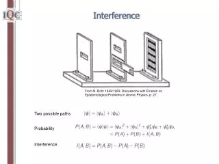
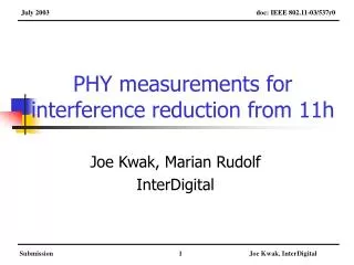
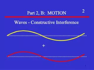
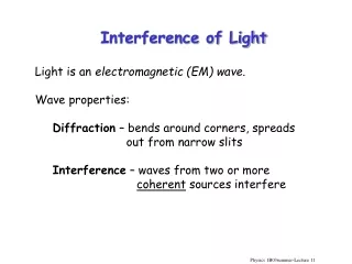
International Journal of Trend in Scientific Research and Development (IJTSRD) Volume: 3 | Issue: 3 | Mar-Apr 2019 Available Online: www.ijtsrd.com e-ISSN: 2456 - 6470 Reduction of Interference Vinay Pokharna1, Manisha Kumawat2, Suresh Bhati1 1Student, 2Associate Professor 1,2Electronics and Communications Engineering Department, 1,2Poornima College of Engineering, Jaipur, Rajasthan, India How to cite this paper: Vinay Pokharna | Manisha Kumawat | Suresh Bhati "Reduction of Interference" Published in International Journal of Trend in Scientific Research and Development (ijtsrd), ISSN: 2456- 6470, Volume-3 | Issue-3 , April 2019, pp.1005-1007, URL: https://www.ijtsrd.c om/papers/ijtsrd228 96.pdf Copyright © 2019 by author(s) and International Journal of Trend in Scientific Research and Development Journal. This is an Open Access article distributed under the terms of the Creative Commons Attribution License (CC BY 4.0) (http://creativecommons.org/licenses/ by/4.0) I. Introduction In a run of the mill remote communication framework, circuit loads up, connectors, and transmission lines handle the approaching and outgoing communication signal that enter or leave the framework by means of communication reception apparatus. At high communication speeds, the conductive ways of the framework's circuit sheets, connectors, and transmission lines pickup and emanate electromagnetic energy that can meddle with the execution of the framework's accepting and sending apparatuses. ABSTRACT A remote correspondence framework can involve at least two antennas that meddle with each other through free space coupling, surface wave crosstalk, dielectric spillage, or other interference impact. The interference impact can deliver an obstruction motion on one of the reception apparatus. A crossing out gadget can stifle antenna obstruction by producing a gauge of the interference flag and subtracting the gauge from the interference flag. The retraction gadget can produce the gauge dependent on examining signals on a reception apparatus that creates the obstruction or on a receiving wire that gets the impedance. The wiping out gadget can include a model of the crosstalk impact. Transmitting test motions on the communication framework can characterize or refine the model. KEYWORDS: interference, Crosstalk, ACI, EMI IJTSRD22896 a signal in a problematic way. It happens as movements along a channel between its source and beneficiary. The term is regularly used to allude to the expansion of undesirable signs to a valuable signal. Types of Interference in Antenna Co-Channel Interference(CCI), also known as Crosstalk. Adjacent-Channel Interference(ACI) Inter symbol Interference The emanated vitality from one radio wire or a related conductive channel unfortunately couples into or is gotten by another reception apparatus or its related channel. This unwanted exchange of signal vitality, known as "crosstalk" or "interference," can bargain signal or information integrity. Crosstalk normally happens in a bidirectional way in that a solitary reception apparatus or channel can both transmit vitality to at least one different radio wires or channels and get vitality from at least one different receiving wires or channels. In multi-reception apparatus frameworks, regardless of whether the receiving wires convey unmistakable or ill defined signs, keeping up a sufficient dimension of antenna isolation is commonly attractive. A base separation of 15 dB is normally viewed as satisfactory for generally applications. Fig1 Interference III. Co-channel different radio transmitters using the same channel. Co-channel obstruction can be brought about by numerous variables from climate conditions to managerial and configuration issues. Co-channel impedance might be constrained by various radio asset management schemes. Co-Channel Interference interference or CCI is crosstalk from two II. In electronic communications, particularly with respect to telecommunications, interference is that which changes Interference and Types @ IJTSRD | Unique Paper ID – IJTSRD22896 | Volume – 3 | Issue – 3 | Mar-Apr 2019 Page: 1005
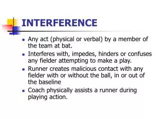
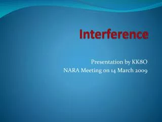
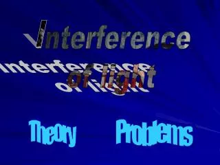
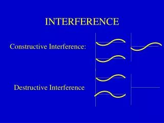
International Journal of Trend in Scientific Research and Development (IJTSRD) @ www.ijtsrd.com eISSN: 2456-6470 Reduction Broadcast controllers every now and again deal with the broadcast range so as to limit neighbouring channel obstruction. For instance, in North America, FM radio stations in a solitary locale can't be authorized on adjoining frequencies. If a station is authorized on 99.5 MHz in a city, the principal neighboring frequencies of 99.3 MHz and 99.7 MHz can't be utilized anyplace inside a specific separation of that station's transmitter. The second-nearby frequencies of 99.1 MHz and 99.9 MHz are confined to particular utilizations, for example, low- control stations. Comparative limitations once in the past connected to third-contiguous frequencies also (for example 98.9 MHz and 100.1 MHz in the precedent above), however these are never again watched. The second method of reducing Adjacent Channel interference is by using modulation plans which have little out band radiation. V. Inter symbol Interference In telecommunication, Inter symbol interference (ISI) is a structure of distortion of a signal in which one symbol interferes with subsequent symbols. This is an undesirable effect as the previous symbol have comparative impact as noise, subsequently making the communication less dependable. The spreading of the pulse past its designated time interim makes it meddle with neighboring pulses. ISI is normally brought about by multipath spread. The nearness of ISI in the framework presents blunders in the choice gadget at the collector yield. Fig2 Co-Channel Interference Reduction A co-channel obstruction decrease strategy utilizing a Constant modulus calculation (CMA) adaptive array antenna exhibit is proposed. When we apply an adaptive cluster antenna to lessen co-channel impedance, a co-channel obstruction signal may be caught. In this technique, the copy of the obstruction signal is produced and afterward dispensed with from the received signal, and along these lines the ideal signal can be acquired. PC re-enactment results affirm that a CMA adaptive cluster antenna that utilizes this strategy can decrease co-channel impedance in excess of an ordinary CMA versatile array antenna. Fig3 CMA Adaptive Array Reduction IV. Adjacent channel interference (ACI) is interference caused by extraneous power from a signal in an adjacent channel. ACI might be brought about by insufficient separating, (for example, inadequate shifting of unwanted modulation products in FM systems), improper tuning or poor recurrence control (in the reference channel, the meddling channel or both). Adjacent-Channel Interference Fig5 Inter Symbol Interference Reduction Separate symbols in time with guard periods. Apply an equalizer at the collector, that, comprehensively, Endeavour’s to fix the impact of the channel by applying an inverse filter. Apply a sequence detector at the collector, that Endeavour’s to gauge the succession of transmitted images utilizing the Viterbi calculation. Plan frameworks to such an extent that the drive reaction is short enough that almost no vitality from one symbol spreads into the following symbol. Fig4 Adjacent Channel Interference @ IJTSRD | Unique Paper ID - IJTSRD22896 | Volume – 3 | Issue – 3 | Mar-Apr 2019 Page: 1006
International Journal of Trend in Scientific Research and Development (IJTSRD) @ www.ijtsrd.com eISSN: 2456-6470 speed, wavelength, assimilation, or impedance. A vibrating crystal makes the ultrasonic waves that are transmitted into the medium. The waves strike a reflector set parallel to the crystal. The waves are then reflected back to the source and estimated. VII. The loss in the transmission line harms link budget execution since energy is being dispersed as heat in the transmission line. That equivalent loss notwithstanding, brings down the energy that gets to a transmit antenna and further declines the energy returning back to the radio from the receiving antenna. Reference [1]Reduction of interference between two neighboring antennas by a modulated metasurface N. Kumutha ; K. Hariharan ; B. Manimegalai 2015 IEEE International WIE Conference on Electrical and Computer Engineering (WIECON-ECE) Year: 2015 Disadvantages Fig6 Reduction of ISI VI. 1.Optical Interferometry: Thomas Young's double slit interferometer in 1803 showed interference borders when two little openings were enlightened by light from another little gap which was lit up by daylight. Young could appraise the wavelength of various hues in the range from the dividing of the edges. 2.Radio Interferometry: In 1946, a procedure called galactic interferometry was created. The majorities of the telescopes in the cluster are broadly isolated and are typically associated together utilizing coaxial link, waveguide, optical fibre, or other sort of transmission line. Interferometry expands the total signal collected 3.Acoustic Interferometry: An acoustic interferometer is an instrument for estimating the physical attributes of sound wave in a gas or fluid. It might be utilized to gauge Application [2]Mutual coupling reduction between two patch antennas using a new miniaturized soft surface structure S. Abushamleh ; H. Al-Rizzo ; A. Abbosh ; Ahmed A. Kishk 2013 IEEE Antennas and Propagation Society International Symposium (APSURSI) Year: 2013 [3]Mutual Coupling Reduction Between Micro strip Patch Antennas Using Slotted-Complementary Split-Ring Resonators Mohammed M. Bait-Suwailam ; Omar F. Siddiqui ; Omar M. Ramahi IEEE Antennas and Wireless Propagation Letters Year: 2010 , Volume: 9 @ IJTSRD | Unique Paper ID - IJTSRD22896 | Volume – 3 | Issue – 3 | Mar-Apr 2019 Page: 1007