Download
1 / 6
60 likes | 70 Views
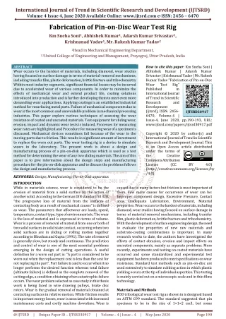
Every component has certain lifetime in order to increase their lifetime different manufacturing methods are to be used. The studies indicate that the greatest stress appears on the upper end of the piston pin and this stress concentration is one of the mainly reason for fatigue failure of piston pin. In order to increase the fatigue life, automobile industries tries to fabricate the piston pin in various methods. Since the pin is subject to fluctuating kind of load during its service condition, the estimation of the life of the piston pin is very much essential. Also this exercise help us to identify which method of production has yield more life. Our main objective is to design and fabricate a test rig for fatigue test of piston pin. The fixtures for simulating actual service condition is modeled and analyzed using CATIA and ANSYS software's and based on the results the dimensions for each component are evolved. Also proved that the fixture developed in this works satisfactorily and the given piston pin serves for more than 300000 cycles for the given loads. R. Sampathkumar | P. Srirajarajan "Design Analysis & Fabrication of Test Rig for Piston Pin Fatigue Life Assessment" Published in International Journal of Trend in Scientific Research and Development (ijtsrd), ISSN: 2456-6470, Volume-2 | Issue-5 , August 2018, URL: https://www.ijtsrd.com/papers/ijtsrd15896.pdf Paper URL: http://www.ijtsrd.com/engineering/mechanical-engineering/15896/design-analysis-and-fabrication-of-test-rig-for-piston-pin-fatigue-life-assessment/r-sampathkumar<br>

E N D
International Research Research and Development (IJTSRD) International Open Access Journal Design Analysis & Fabrication of Test Rig for Piston Pin Fatigue Life Assessment Sampathkumar1, P. Srirajarajan2 1Lecturer Senior Grade, 2Lecturer Department of Mechanical Engineering, Nachimuthu Polytechnic College, Pollachi, TamilNadu, India International Journal of Trend in Scientific Scientific (IJTSRD) International Open Access Journal ISSN No: 2456 ISSN No: 2456 - 6470 | www.ijtsrd.com | Volume 6470 | www.ijtsrd.com | Volume - 2 | Issue – 5 Design Analysi Piston Pin Fatigue R. Sampathkumar s & Fabrication of Test Rig for 1 Department of Mechanical Engineering, Nachimuthu Polytechnic College, connecting rod. This hinged joint transfer direc gas thrust from the piston to the connecting allows the rod to pivot relative to the cylinder axis with an oscillating motion. Piston pin is the component in all kinds of engines (diesel, gasoline, 2 strokes and 4 strokes). It functions a between the piston and its gadget and bears the twist and friction incurred by the running engine. It fastens the piston and the connecting rod severally and securely, but at the same time permitting enough play for the free angular movement according to the requirements of kinematics of the engine assembly.. Hence, mobile operators find meeting these new demands in wireless cellular networks in evitable. To do this cost paradigm shift in cellular network i deployment is occurring away from traditional (expensive) high-power tower and towards heterogeneous elements. Examples of heterogeneous elements include microcells, pico femto-cells, and distributed antenna syste radio heads), which are distinguished by their transmit powers/ coverage areas, physical size, backhaul, and propagation characteristics. The resulting network, referred to as heterogeneous network (Het Net), helps in maintaining the quality of larger number of users by reusing the spectrum. larger number of users by reusing the spectrum. ABSTRACT Every component has certain lifetime in order to increase their lifetime different manufacturing methods are to be used. The studies indicate that greatest stress appears on the upper end of the piston pin and this stress concentration is one of the mainly reason for fatigue failure of piston pin. In order to increase the fatigue life, automobile industries tries to fabricate the piston pin in various methods. Since the pin is subject to fluctuating kind of load during its service condition, the estimation of the life of the piston pin is very much essential. Also this exercise help us to identify which method of production has yield more life. Our main objective is to design and fabricate a test rig for fatigue test of piston pin. The fixtures for simulating actual service condition is modeled and analyzed using CATIA and ANSYS software’s and based on the results the dimensions for each component are evolved. Also proved that the fixture developed in this works satisfactorily and the given piston pin serves for more than 300000 cycles for the given loads. Keywords: Articulator Block, Fatigue, FEA, L Piston Pin, Test Rig INTRODUCTION A gudgeon pin or piston pin or wrist pin is the connection holding the piston on to the connecting rod. It is supported in holes bored in the piston at right angles to the piston axis at about mid-height position, and the center portion of the gudgeon through the connecting-rod small-end eye. The fig 1 and 2 shows the position of piston pin in the cylinder piston arrangement. The piston pin is the vital mechanical link that hinges the piston to the mechanical link that hinges the piston to the Every component has certain lifetime in order to increase their lifetime different manufacturing methods are to be used. The studies indicate that the greatest stress appears on the upper end of the piston pin and this stress concentration is one of the mainly reason for fatigue failure of piston pin. In order to increase the fatigue life, automobile industries tries to connecting rod. This hinged joint transfer directly the gas thrust from the piston to the connecting-rod and allows the rod to pivot relative to the cylinder axis with an oscillating motion. Piston pin is the component in all kinds of engines (diesel, gasoline, 2 strokes and 4 strokes). It functions as the linkage between the piston and its gadget and bears the twist and friction incurred by the running engine. It fastens the piston and the connecting rod severally and securely, but at the same time permitting enough play for the free angular movement of the connecting rod according to the requirements of kinematics of the engine assembly.. Hence, mobile operators find meeting these new demands in wireless cellular To do this cost-effectively, a paradigm shift in cellular network infrastructure deployment is occurring away from traditional power tower-mounted base stations and towards heterogeneous elements. Examples of heterogeneous elements include microcells, pico-cells, cells, and distributed antenna systems (remote radio heads), which are distinguished by their transmit powers/ coverage areas, physical size, backhaul, and rious methods. Since the pin is subject to fluctuating kind of load during its service condition, the estimation of the life of the piston pin is very much essential. Also this exercise help us to identify which method of production has r main objective is to design and fabricate a test rig for fatigue test of piston pin. The fixtures for simulating actual service condition is modeled and analyzed using CATIA and ANSYS software’s and based on the results the dimensions for are evolved. Also proved that the fixture developed in this works satisfactorily and the given piston pin serves for more than 300000 cycles Articulator Block, Fatigue, FEA, L-Plate, The resulting network, referred to as heterogeneous network (Het Net), helps in maintaining the quality of service (QoS) for a A gudgeon pin or piston pin or wrist pin is the connection holding the piston on to the connecting rod. It is supported in holes bored in the piston at right height position, and the center portion of the gudgeon-pin passes end eye. The fig 1 and 2 shows the position of piston pin in the cylinder piston arrangement. The piston pin is the vital @ IJTSRD | Available Online @ www.ijtsrd.com @ IJTSRD | Available Online @ www.ijtsrd.com | Volume – 2 | Issue – 5 | Jul-Aug 2018 Aug 2018 Page: 641
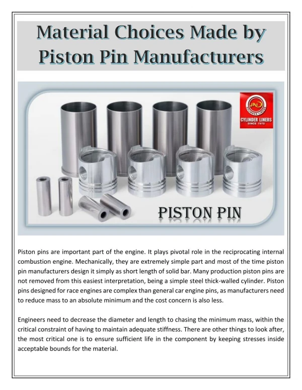
International Journal of Trend in Scientific Research and Development (IJTSRD) ISSN: 2456 in Scientific Research and Development (IJTSRD) ISSN: 2456 in Scientific Research and Development (IJTSRD) ISSN: 2456-6470 Figure 1: Location of Gudgeon Pin Figure 1: Location of Gudgeon Pin Figure 4: Gudgeon Pin with Various Case Depth and Length In chasing minimum mass, engineers look to decrease length and diameter, within the important constraint of having to maintain adequate stiffness. There are other constraints we need to respect, the most important being to ensure sufficient life in the component by keeping stresses within acceptable bounds for the material in question. Though simple in appearance, without moving parts, it must be recognized as a precision engineered component. This is because it has to satisfy several conflicting requirements: It must combine strength with lightness; it must be close fitting but with freedom of movement, and it must resist wear without scuffing. Figure 4: Gudgeon Pin with Various Case Depth and Length In chasing minimum mass, engineers look to decrease length and diameter, within the important constraint of having to maintain adequate stiffness. There are other constraints we need to r important being to ensure sufficient life in the component by keeping stresses within acceptable bounds for the material in question. Though simple in appearance, without moving parts, it must be recognized as a precision engineered compon is because it has to satisfy several conflicting requirements: It must combine strength with lightness; it must be close fitting but with freedom of movement, and it must resist wear without scuffing. Requirements of piston pin are Adequate rigidity to keep stressing of the piston pin bore and pin bore support at an acceptable level. This rigidity consists of bending deflection. Adequate rigidity to provide uniform bearing loads in pin bore area. Sufficient bearing area from the length and diameter to keep bearing pressure in the piston pin bore and connecting rod bore at an acceptable level. Light-weight to reduce the effects of inertia forces. Good outer diameter and surface finish enhancing lubrication with piston and connecting rod mating surfaces. Adequate material and heat treat to provide structural strength and good wear characteristics The surface of the pin is extremely smooth, almost mirror like. This is because it is a bearing. A smoother finish causes less friction and less wear on the journals of both the connecting rod and piston. The pin is lubricated with oil that is splashing around to do the crank shaft rotation. Figure 2: Cut Section of Piston Assembly Piston pins play a vital, literally pivotal, role in the reciprocating internal Mechanically they are component and, in their most basic form, could be a simple, short length of solid bar. But many production piston pins are not far removed from this simplest interpretation, being a very plain steel thick cylinder. A commonly used piston pin is shown in fig.3.They vary in size and material makeup according to the particular engine, but in general they are made from medium to high quality hard en steel tube. The tube is used because the vast majority of the stresses associated with the firing of the piston are carried by the infinitesimal elements located near the outer surface. The piston pins made up of various diameter and length are shown in fig.4.Another reason for the use of a hollow pin is weight consideratio With the pin located away from the crank shaft, a heavier pin would cause more moment hence less work would be transferred to the crank. More work would have to be done moving the heavier upper piston assembly back and forth. Figure 2: Cut Section of Piston Assembly Piston pins play a vital, literally pivotal, role in the reciprocating internal cally they are component and, in their most basic form, could be a simple, short length of solid bar. But many production piston pins are not far removed from this simplest interpretation, being a very plain steel thick-walled A commonly used piston pin is shown in fig.3.They vary in size and material makeup according to the particular engine, but in general they are made from medium to high quality hard en steel tube. The tube is used because the vast majority of associated with the firing of the piston are carried by the infinitesimal elements located near the outer surface. The piston pins made up of various diameter and length are shown in fig.4.Another reason for the use of a hollow pin is weight considerations. With the pin located away from the crank shaft, a heavier pin would cause more moment hence less work would be transferred to the crank. More work would have to be done moving the heavier upper combustion an extremely an extremely combustion engine. simple simple engine. Requirements of piston pin are dity to keep stressing of the piston pin bore and pin bore support at an acceptable level. This rigidity consists of bending deflection. Adequate rigidity to provide uniform bearing Sufficient bearing area from the length and er to keep bearing pressure in the piston pin bore and connecting rod bore at an acceptable weight to reduce the effects of inertia Good outer diameter and surface finish enhancing lubrication with piston and connecting rod mating Adequate material and heat treat to provide structural strength and good wear characteristics The surface of the pin is extremely smooth, almost mirror like. This is because it is a bearing. A smoother finish causes less friction and less wear on the journals of both the connecting rod and piston. The pin is lubricated with oil that is splashing around Figure 3: Typical Gudgeon Pin geon Pin @ IJTSRD | Available Online @ www.ijtsrd.com @ IJTSRD | Available Online @ www.ijtsrd.com | Volume – 2 | Issue – 5 | Jul-Aug 2018 Aug 2018 Page: 642
International Journal of Trend in Scientific Research and Development (IJTSRD) ISSN: 2456-6470 Generally the pin should have following properties Strength and rigidity Durability and a high fatigue threshold Light-weight to keep inertia forces to a minimum Superior surface finish for good bearing properties Within the piston assembly Cost-effective production The finish and size of gudgeon-pins are very closely controlled. A loose gudgeon-pin in the piston or in the connecting rod causes a rattle during the engine operation. If the pin is too tight in the piston, it restricts piston expansion along the pin diameter which produces piston scuffing. Gudgeon-pin operating clearances are usually about 0.0075 mm, which is critical for quiet running and long life. Piston pin holes located in the piston have an offset of approximately 1.57 mm from the piston center line. Pin offset reduces piston slap and noise, which is created due to crossover action as the large end of the connecting rod swings past both upper and lower dead centers. 2.0 MATERIALS AND METHODS The most common material for piston pins in general is steel; the surface is often hardened to improve wear resistance, and the choice of hardening method will dictate the choice of material. There are two main choices for hardening - carburizing (also known as case hardening) and nitride hardening. Both have a beneficial side-effect of compressive residual stresses to the surfaces of the part, which in turn improve fatigue resistance compared to a part without these stresses. Carburizing steels are characterized by low carbon content and additions of manganese, nickel and chromium; it is the low carbon content that allows diffusion of carbon into the surface. Nitrating steels have additions of elements such as chromium, aluminum and titanium, which are strong nitride formers. There are a number of higher strength steels not necessarily designed for nitride hardening, but which it is certainly possible to nitride and which would make excellent candidates for piston pins. They are usually made from low-carbon case- hardened steel of composition 0.15% carbon, 0.3% silicon, 0.55% manganese, and the balance 99% iron. This steel is carburized at a temperature of 1153 to 1203 K, refined at 1143 to 1173 K and then hardened by oil quenching from 1033 to 1053 K. Finally it is tempered at a temperature below 433 K. Thegudgeon- pin bosses in the piston experiences a temperature of about 393 to 423 K for both petrol and diesel engines. Also the temperature rise due to friction between the pin and the bosses is in the order of 20 to 30 K. Therefore the gudgeon-pin has to withstand a temperature of about 431 to 453K.The wear resistance of all kinds of steel pins has been improved by using hard, thin coatings. There are various kinds of DLC that have been shown to be beneficial, and pins with these kinds of coating have been in reasonably widespread use in many categories of motorsport for well over a decade. Steel is not the only choice for piston pins though; a number of companies offer titanium pins. Titanium has a much lower density than that of steel, although its elastic modulus (a measure of stiffness) is also low compared with steel. Titanium Ti-6Al-4V is often used, although pins made from Ti-17 (Ti-5Al-2Sn- 4Mo-2Zr-4Cr) are also commercially available. We should not, however, expect to replace an optimized steel piston pin with one of the same dimensions made from titanium, and expect to find success. Titanium has particularly poor wear behavior in sliding contacts, so titanium pins would need to be coated to achieve an acceptable level of durability. Again DLC is often used here, but pins are also marketed which have a titanium nitride coating. 2.1. Design of Piston Pin Design of any piston pin requires appropriate parameters such as length, inner and outer diameters. These parameters are depends on piston diameter, connecting rod width and bearing pressure. The fig.5 shows the geometry of piston pin in various views. imparting significant Figure 5: geometry of piston pin in various views Load on the piston pin due to bearing pressure = Bearing pressure × Bearing area = Pb1 × do × l1 N…………eqn (1) Here, Pb1 –Bearing pressure at the small end of the connecting rod bushing in N/mm2 @ IJTSRD | Available Online @ www.ijtsrd.com | Volume – 2 | Issue – 5 | Jul-Aug 2018 Page: 643
International Journal of Trend in Scientific Research and Development (IJTSRD) ISSN: 2456-6470 Connecting Rod Articulator block In order to accomplish this need, a pair of L plates is used to switch the conditions of piston. A base plate is handled whose job is to rigidly hold the L plates. A connecting rod plays a role of transferring the load to the piston pin. An articulator block is the connection between connecting rod and articulator. 2.4 L plates A pair of L plates was used whose role is to hold the Gudgeon pin rigid as inside the piston. Necessary space is provided between the two L plates in order to place the connecting rod inside. The fig 7 shows the L plate do l1 – Outside diameter of piston pin in mm – Length of pin in the bush of the small end of the connecting rod in mm Outer diameter of pin (based on bearing) Outer diameter of piston pin is calculated based on bearing pressure length of gudgeon pin bearing l1 = 0.35-0.45D do = Fmax / l1 Pbm…...eqn(2) Bearing pressure (pb) (MN/m2) 12.4 15 15.7 For Automotive Engines Table.1 Bearing Pressures For Different Engines 2.2 Inner diameter of pin (based on bending) Inner diameter of pin is determined by considering bending stress due to gas load when loaded uniformly over length and supported at center of the boss. Engines For Gas Engines For Oil Engines Figure 7: L plate 2.5 Base Plate Base plate forms the base for the whole test rig. Therefore the base plate should be designed and modeled in a way that it should transfer the vibrations occurring in the test rig to the machine bed effectively. The base plate with necessary dimensions is represented in the fig 8. Fig.6 Loading of Piston Pin Bending stress due to gas load ? ? But Maximum bending moment M = Fmax× D / 8 Therefore, Z = Fmax× D / 8 σb Z = π (do4 – di4) / 32 do 2.3Modeling / Preprocessing The goals of preprocessing is to develop an appropriate model which satisfies the necessary working conditions, assign properties and apply boundary conditions in the form of constraints and loads. In this project the piston and connecting rod assembly is replaced with a suitable test rig. This test rig should fulfil the necessary conditions as in the case of piston cylinder arrangement. The test rig consists, Pair of L plates Base plate ………eqn (3) Z = …eqn(4) ………….eqn (5) suitable material Figure 8: Base Plate 2.6 Connecting Rod Connecting rod is the intermediate component whose function is to transfer the fatigue load from articulator block to the Gudgeon pin. A typical Connecting rod model in shown in the fig.9.The connecting rod used for fatigue test has to be slightly modified in the big @ IJTSRD | Available Online @ www.ijtsrd.com | Volume – 2 | Issue – 5 | Jul-Aug 2018 Page: 644
International Journal of Trend in Scientific Research and Development (IJTSRD) ISSN: 2456 in Scientific Research and Development (IJTSRD) ISSN: 2456 in Scientific Research and Development (IJTSRD) ISSN: 2456-6470 end in order to clamp it directly to the articulator block. end in order to clamp it directly to the articulator used to verify the material and dimensions of the required test rig. ANSYS Workbench is used for perform the finite element analysis. 3D models of the components are generated in Creo Parametr These models are imported to Workbench as IGES files. Then the models meshed and boundary conditions are given based on the conditions. For the fatigue test, a compressive load of 45KN and a tensile load of 15KN are applied. material and fatigue parameters the models are solved. The following figures show the boundary condition given and the results obtained in stress, displacement, and fatigue determinants such as life, damage and safety factor. 3.2 Boundary Conditions for L The imported model with being boundary conditions is applied. Fixed support (A) is given in base hole, Force B of 45kN is given to the top side of pin which is compressive and Force C of 15kN is a tensile load which is given to the bottom of pin. Fri contact is established between outer surface of pin and inner surface of boss of fixture. inner surface of boss of fixture. used to verify the material and dimensions of the ANSYS Workbench is used for perform the finite element analysis. 3D models of the components are generated in Creo Parametric 2.0. These models are imported to Workbench as IGES files. Then the models meshed and boundary conditions are given based on the conditions. For the fatigue test, a compressive load of 45KN and a tensile After the insertion of material and fatigue parameters the models are solved. The following figures show the boundary condition given and the results obtained in stress, displacement, and fatigue determinants such as life, damage and Figure 9: Connecting Rod Figure 9: Connecting Rod 2.7 Articulator Block Articulator block forms the connection between the articulator end of the actuator and the big end of connecting rod. Fig10 shows the articulator block with dimensioning. Articulator block forms the connection between the articulator end of the actuator and the big end of shows the articulator block Boundary Conditions for L Plate The imported model with being boundary conditions (A) is given in base hole, Force B of 45kN is given to the top side of pin which is compressive and Force C of 15kN is a tensile load which is given to the bottom of pin. Frictionless contact is established between outer surface of pin and Figure 10: Articulator Block Figure 10: Articulator Block 2.8 Test Rig Assembly The testrig arrangement starts with base plate and two L plates were fixed rigidly to it. The Gudgeon pin is placed between the L plates and the connecting rod’s small end passes through the gudgeon pin. Big end of the connecting rod is fixed to the articulator block. The actuator end is connected to the articulator block as shown in the fig.11. starts with base plate and two L plates were fixed rigidly to it. The Gudgeon pin is placed between the L plates and the connecting rod’s small end passes through the gudgeon pin. Big end of the connecting rod is fixed to the articulator block. r end is connected to the articulator block Figure 12: boundary Conditions of L Figure 12: boundary Conditions of L- Plate Figure 13: Boundary Conditions of Articular Block Figure 13: Boundary Conditions of Articular Block 3.3. Von-Misses Stress for L Plate Maximum stress of 396 MPa is found near the boss of L plate and the minimum value is 0.01 MPa. L plate and the minimum value is 0.01 MPa. Misses Stress for L Plate MPa is found near the boss of Figure 11: Test Rig Assembly Model Figure 11: Test Rig Assembly Model RESULTS AND DISCUSSION 3.1. FEA of Fixture and Piston Pin The objective of FEA is to investigate stresses, displacements experience by the fixture set piston pin. The results obtained by this analysis can be piston pin. The results obtained by this analysis can be The objective of FEA is to investigate stresses, displacements experience by the fixture setup and Figure 13: Von-Misses Stress for L Misses Stress for L- Plate @ IJTSRD | Available Online @ www.ijtsrd.com @ IJTSRD | Available Online @ www.ijtsrd.com | Volume – 2 | Issue – 5 | Jul-Aug 2018 Aug 2018 Page: 645
International Journal of Trend in Scientific Research and Development (IJTSRD) ISSN: 2456-6470 3.4 Deformation Result for L-Plate The deformation results for the L plates. Maximum deformation of 0.02 mm is found at the mid portion of pin and a minimum value of 0 at the base. Figure 17: deformation Result for Articulator Block CONCLUSION Design of test rig is done in CATIA V5 and analysis is performed in ANSYS Workbench 14. From the analysis, values of stress and deformation are in considerable limits with the maximum safety factor of 15. The same model is manufactured and heat treated for the specified hardness value. Fatigue test is conducted to the piston pin in the test rig for 3 lakhs cycles. Test results shows that the fixture is capable for testing the piston pin. REFERENCES 1.V. RamamurtiandS. considerations of Gudgeon pin in reciprocating air compressors by semi analytic approach” Vol. 4(3), pp. 75-88, 2012 Figure 14: Deformation of L-Plate 3.5 Boundary Conditions for Articulator Block The articulator block is imported in the Ansys workbench and the boundary conditions are shown in fig Fixed support(A) is given to the mating part of connecting rod, Force B of 45KN and a force C of 15 KN is given to the boss. Sridhar, "Design 2.Yanxia Wang and HuiGao, "Research on Optimization for the Piston Pin and the Piston Pin Boss", The Open Mechanical Engineering Journal, Vol. 5, pp. 186-193, 2011. Figure 15: Boundary Conditions for Articulator Block 3.6 Von-Misses Stress for Articulator Block The von misses stress for the given articulator block is shown in the fig 16 Maximum stress value of 250MPa is found near the boss at the base and the minimum value is 0.1 MPa. 3.7 Deformation Result for Articulator Block The fig 17shows the deformation results for the articulator block for the given boundary condition. Maximum deformation of 0.02 mm is found at top side of part and the minimum value of 0 is found near the base. 3.Andrew Homick and Aaron Turbeville, " Wrist Pin & Crank Pin Journal Bearin Design, vol. 31, pp. 537-550, 2011. 4.T. Connolly and E. Yagle, "Modelling and Identification of the combustion pressure process in internal combuston engines", Mechanical systems and Signal processing, Vol. 8(1), pp. 1- 19, 1994. 5.AdilaAfzal Predictions of Forged Steel and Powder Metal Connecting Rods", pp. 1-179, 2004. “Fatigue Behaviour and Life Figure 16: Von-Misses stress of Articular Block @ IJTSRD | Available Online @ www.ijtsrd.com | Volume – 2 | Issue – 5 | Jul-Aug 2018 Page: 646