Download
1 / 9
100 likes | 190 Views
Learn about methods for evaluating remaining fatigue life in space hardware due to random vibrations, essential for ensuring flightworthiness. Includes a prototype hardware program and vibration life section guidance for accurate assessments.

E N D
Fatigue Life Assessment William O. Hughes/7735 Mark E. McNelis/7735 July 22, 2004 Random Vibration Testing of Hardware Tutorial
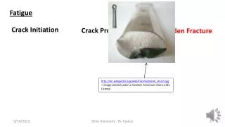
Introduction: Fatigue Life Assessment • Vibration of space-flight hardware, from either ground random vibration testing or launch, fatigues the hardware. Every additional test or launch reduces the remaining fatigue life of that hardware. • A methodology to provide guidance on establishing the qualification-test “demonstrated fatigue life” of a hardware design and estimating the remaining vibration fatigue life in identically-designed flight acceptance hardware units was provided in the Lewis Management Instruction (LMI) 8070.2, March 19, 1993. That methodology may be used to demonstrate that sufficient useful life remains in the flight hardware unit for (re)test and subsequent flight. • This methodology is derived from the “Inverse Power Law Model” and the “Fatigue Damage Model Based upon the S-N Curve” • However, the relationship between exposure duration, amplitude and fatigue damage inflicted on hardware is non-linear and material dependent, and one needs to use caution in judging the flightworthiness of hardware exposed to high frequency random vibration environments. Random Vibration Testing of Hardware Tutorial
Notes taken from “Dynamic Environmental Criteria”NASA-HDBK-7005, March 13, 2001 Inverse Power Law Model (time-to-failure related to rms dynamic loading) Equivalency Equation for two rms dynamic loads and times Special case of the inverse power law describing the S-N curve (ignoring the fatigue limit) N = number of loading cycles to failure S = peak stress b and c are material constants Idealized S-N Curve for Structural Materials Random Vibration Testing of Hardware Tutorial
Fatigue Life Assessment Requires Prototype Hardware Program • Prototype programs allows an assessment to be made of remaining “fatigue life”: • Qualification testing of the qualification hardware establishes the “test demonstrated fatigue life” for the hardware design. • The identically-designed flight hardware may confidently be acceptance tested and launched, if these events do not extend beyond the previously demonstrated fatigue life. • Any remaining fatigue life can be “allotted” to additional ground tests, reflights, etc. • Protoflight programs have no test demonstrated fatigue life. • Unknown remaining fatigue life. Random Vibration Testing of Hardware Tutorial
“Vibration Life Section” from LMI 8070.2 • “The following formulation for determining vibration life is offered as guidance to be used when no alternate or preferred method is known by the project.” • “(1) The allowable accumulated duration of acceptance test vibration and flight vibration of any flight hardware, for which a vibration qualification test has been performed, shall not exceed 30 percent of the previously demonstrated capability at the equivalent acceptance test amplitude. Prior demonstration at amplitudes greater than acceptance test amplitudes add to the capability in proportion to the time of exposure and to the ratio of the RMS amplitude raised to the power b, where b is the inverse slope of stress verses number of cycles fatigue curve (i.e., the “S-N” curve) for the most fatigue critical material in the item. This relationship is formulated as: • TA = 0.3 [ TO (GO/GA)b + T1 (G1/GA)b ] Random Vibration Testing of Hardware Tutorial
“Vibration Life Section” from LMI 8070.2 (cont.) • TA = 0.3 [ TO (GO/GA)b + T1 (G1/GA)b ] • Where: • TA = Maximum time of flight or laboratory vibration at acceptance test amplitudes allowed on flight equipment prior to last flight; that is, one flight remains when TA = 0. • TO = Minimum time of vibration at qualification amplitudes previously demonstrated without fatigue failure on equipment of identical design. • T1= Minimum time of vibration at acceptance test amplitudes previously accumulated on the same equipment that was subjected to To. • GO= Vibration acceleration qualification amplitude (Grms). • G1= Vibration acceleration acceptance test amplitude (Grms) previously applied to the demonstration unit for the duration T1. • GA= Vibration acceleration acceptance test amplitude (Grms) to which flight equipment is subjected and which must not exceed G1.” • b = fatigue exponent • “(2) This relationship should be applied on a per axis basis and is appropriate only when the spectral shapes are identical for each vibration acceleration amplitude. If the value of b is not known, then a value of b = 2.4 shall be used.” Random Vibration Testing of Hardware Tutorial
Example: Fatigue Life Calculation • Assume Maximum Expected Flight Environment (MEFL) is 3.0 Grms for a flight launch duration of 0.5 minutes • Utilizing the Prototype Hardware Program Test Philosophy (the combining of workmanship test levels with these flight-based levels is ignored for this example): • Qualification Unit is tested for 2 minutes at 4.23 Grms (MEFL + 3 dB; 2 minutes/axes) • Acceptance Flight Unit tested for 1 min at 2.13 Grms (MEFL – 3dB; 1 minute/axes) • Then, • TO = 2 minutes, GO = 4.23 Grms, • T1 = 0 (no acceptance level testing on Qualification Unit), G1 = 2.13 Grms, • GA = 2.13 Grms, b = 2.4 (assume copper wire), and: • TA = 0.3 [ 2(4.23 / 2.13)2.4 + 0(2.13 / 3.0)2.4 ] = 0.3 (10.38 minutes) • TA = 3.11 minutes Random Vibration Testing of Hardware Tutorial
Example: Fatigue Life Calculation (cont.) • Interpretation of TA= 3.11 minutes: • Qualification Unit has demonstrated that Acceptance Flight Unit (design) can survive vibration at the acceptance test level (of 2.13 Grms) for 3.11 minutes. • Fatigue Life Remaining on Acceptance Flight Unit at acceptance test levels (after accounting for performing normal acceptance vibration test of flight unit and launching flight unit) = 0.97 minutes, since: • Fatigue Life Remaining = TA – 1 acceptance test – 1 flight = (3.11 – 1.00 – 1.14) minutes = 0.97 minutes • Since 1 acceptance test = 1.0 minute at the 2.13 Grms acceptance test level • Since 1 flight (at 3.0 Grms for 0.5 minute) = 1.14 minutes (TAe) at the 2.13 Grms acceptance level, derived from the (inverse power law) equivalency equation: • TAe=Tf (Gf/GA)b, where TAe= the equivalent acceptance test time for one flight, Tf= flight duration, Gf=vibration acceleration flight amplitude (Grms), GA=vibration acceleration acceptance test amplitude (Grms) Random Vibration Testing of Hardware Tutorial
Additional Notes on Fatigue Life • Hardware may have more (unknown) life than indicated (beyond what was demonstrated in qualification test) • The fatigue exponent “b” will vary depending upon the material under stress. Some possible values include: b=2.4 for electronic equipment (assumes copper wire) b=4.0 for complex electrical and electronic equipment items b=8.0 for un-notched steel and aluminum alloys structures, under random vibration loading • Other types of failure modes besides “fatigue based on S-N curve” are possible (such as first passage critical threshold failures, or fatigue based on crack growth). Random Vibration Testing of Hardware Tutorial