Download
1 / 6
60 likes | 154 Views
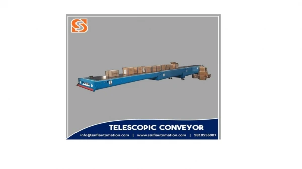
A conveyor system is a common piece of mechanical handling equipment that moves materials from one location to another. Many kinds of conveying systems are available, and are used according to the various needs of different industries. The purpose of this project is to improve the existing conveyor machine that located at the methodology lab in AL FALAH UNIVERSITY. This paper gives a review of the belt conveyor technology that focuses on the types of drives and the control system or the controller of the belt conveyor using PID controller. This paper highlights the characteristics, performance measure, requirements and the operational procedure of the belt conveyor drives and control systems. Muhammad Shahid | Md Ghaysuddin "Design and Implementation of Conveyor Belt Speed Control using PID for Industrial Applications" Published in International Journal of Trend in Scientific Research and Development (ijtsrd), ISSN: 2456-6470, Volume-3 | Issue-5 , August 2019, URL: https://www.ijtsrd.com/papers/ijtsrd25294.pdf Paper URL: https://www.ijtsrd.com/engineering/electrical-engineering/25294/design-and-implementation-of-conveyor-belt-speed-control-using-pid-for-industrial-applications/muhammad-shahid<br>

E N D
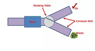
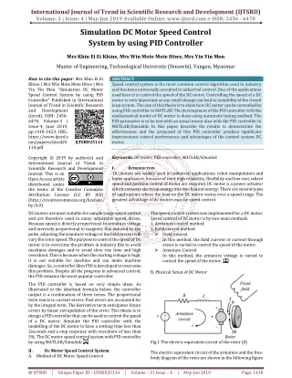
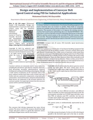
International Journal of Trend in Scientific Research and Development (IJTSRD) Volume 3 Issue 5, August 2019 Available Online: www.ijtsrd.com e-ISSN: 2456 – 6470 Design and Implementation of Conveyor Belt Speed Control using PID for Industrial Applications Muhammad Shahid, Md Ghaysuddin Department of Electrical and Electronics Engineering, Al-Falah Univesity, Dhauj, Faridabad, Haryana, India How to cite this paper: Muhammad Shahid | Md Ghaysuddin "Design and Implementation of Conveyor Belt Speed Control using PID Applications" Published in International Journal of Trend in Scientific Research and Development (ijtsrd), ISSN: 2456- 6470, Volume-3 | Issue-5, August 2019, https://doi.org/10.31142/ijtsrd25294 Copyright © 2019 by author(s) and International Journal of Trend in Scientific Research and Development Journal. This is an Open Access article distributed under the terms of the Creative Commons Attribution License (CC (http://creativecommons.org/licenses/by /4.0) Conveyor systems are commonly used in many industries, including the automotive, agricultural, computer, electronic, food processing, aerospace, pharmaceutical, chemical, bottling and canning, print finishing and packaging. Although a wide variety of materials can be conveyed, some of the most common include food items such as beans and nuts, bottles and cans, automotive components, scrap metal, pills and powders, wood and furniture and grain and animal feed. Many factors are important in the accurate selection of a conveyor system. It is important to know how the conveyor system will be used beforehand.[4] ABSTRACT A conveyor system is a common piece of mechanical handling equipment that moves materials from one location to another. Many kinds of conveying systems are available, and are used according to the various needs of different industries. The purpose of this project is to improve the existing conveyor machine that located at the methodology lab in AL-FALAH UNIVERSITY. This paper gives a review of the belt conveyor technology that focuses on the types of drives and the control system or the controller of the belt conveyor using PID controller. This paper highlights the characteristics, performance measure, requirements and the operational procedure of the belt conveyor drives and control systems. KEYWORDS: Conveyor belt, DC motor, PID Controller, Speed Synchroniser, Laplace transform INTRODUCTION A conveyor system is a common piece of mechanical handling equipment that moves materials from one location to another. Conveyor systems allow quick and efficient transportation for a wide variety of materials, which make them very popular in the material handling and packaging industries [1]. Many kinds of conveying systems are available, and are used according to the various needs of different industries. There are chain conveyors (floor and overhead) as well [2]. Chain conveyors consist of enclosed tracks, I-Beam, towline, power & free, and hand pushed trolleys [3]. Conveyor systems are used widespread across a range of industries due to the numerous benefits they provide. for Industrial IJTSRD25294 pp.284-289, BY 4.0) Controller: Here brief introduction about a process control system has been given. The basic control loop can be simplified for a single-input-single-output (SISO) system as in Fig.1. Here we are neglecting any disturbance present in the system. Fig-2 The controller can have different structure .and different value of variables to achieve desired performance level .the most popular controller are P,.PI,PID ,type controller .more than 90% of industry used PID controller. but here we consider only P and PI. If we assume in put is step signal then equation of controller will be.[5]. PID control action is mathematically represented by the equation Fig. 1 The conveyor belt driving component has motor driven system. The motor used for this purpose should have high torque and good control on speed like induction motor, permanent magnet motor and dc series motor. (1) In (1),Kp is proportional gain, E is the error,Ki is the Integral gain,Kd is the derivative gain and is the time in seconds. @ IJTSRD | Unique Paper ID – IJTSRD25294 | Volume – 3 | Issue – 5 | July - August 2019 Page 284
International Journal of Trend in Scientific Research and Development (IJTSRD) @ www.ijtsrd.com eISSN: 2456-6470 Block diagram for equation (1) is illustrated in Figure 1. Applying Laplace Transform methods to equation (1), we have: Newton’s law which states that the inertial load times the derivative of angular rate equals the sum of all the torques about the motor shaft. By energy conservation, the resultant torque on motor shaft must equal zero[11]. - - Where (t) is the electromagnetic torque T' due to rotational acceleration of the rotor Tw, is torque associated with velocity of rotor, and Tc is the torque of the belt conveyor system. The electromagnetic torque is proportional to the current through the armature winding and is written as: i(t) Where Km is torque constant and is dependent on flux density of the fixed magnets, the reluctance of the iron core, and the number of turns in the armature windings written as Jtot (9) (2) A lag filter is introduced into the block diagram of Figure 1 to filter the derivative action of the PID compensator, and thus, equation (1) yield In (1) is the filter coefficient which sets the location of the pole of the derivative filter. Since a filter has been inserted as part of the PID architecture [6], it could now be termed PID with N-order filter on the derivative term (PID) [7]. Auto- tuning technique was used to tune the PID controller in order to achieve a good balance between performance and parameter variations [8]. Fig -3 represent the electrical circuit of dc motor of conveyor system, has a voltage source (Vs ) across the coil of the armature. The armature coil is described by an inductance (L ) in series with a resistance (R ) in series with induced voltage which opposes the voltage source. A differential equation for the equivalent circuit can be derived using Kirchoff’s voltage law around the electrical loop [9]. Vs - VRa - VLa - Vemf =0 is the torque (10) is (11) Where J tot is the inertia of the rotor and the conveyor system. The torque produced as a result of rotor velocity is written as: (12) (3) Where Kf is the damping coefficient or viscous friction associated with the rotating members of the motor Substituting equations (10), (11) and (12) into (9) results in the following expression [12]. Km i(t) - Jtot - Kf - Tc (13) This equation based on above 2 equation = - i(t) - Fig-3 + Vs(t) (14) The voltage across the resistor is represented below with Ohm’s law being applied. VRa =R I(t) where I is the armature current. The inductor has a voltage across the terminal and this is proportional to the change of current through the coil with respect to time and = - + (15) (4) Design of Belt Conveyor: Torque From equations (12) one needs to explicitly derive the torque, Tc of the entire conveyor system in order to characterize the motor load requirements. In this design, the conveyor is assumed to be coupled directly to the motor pulley or roller, where M1, M2, M3 are mass of bottles, M belt is the mass belt Dm is the diameter of motor pulley,D1 is the diameter of driven pulley and Di is the diameter of idler,Jm is mass inertia of shaft and all rotating components about shaft 1, Jr is the idler mass inertia and is the inertia of the driven pulley and shaft 2. The total amount of mass being transported by the conveyors system involves mass of individual bottles in addition to mass of belt[13]. Mt= M1+ M2+M3+M belt Applying Newton’s second law, Mt can be related to the force necessary to accelerate it. Fe= Mt a In (17), is the effective belt tension and is the linear acceleration of the conveyor belt. In terms of angular measures, the linear acceleration can be expressed as Fe= Dm Mt (5) Finally, the back induced emf can be written as (6) where Kb is the velocity constant determined by the flux density of the permanent magnets, the reluctance of the iron core of the armature, and the number of turns of the armature windings [10]. Vs(t) - Ri(t) - - Kb (16) =0 (7) Vs(t) = Ri(t) - - Kb (8) (17) Mechanical Aspects: Conveyors are constant torque machines. That means a constant level of torque is required to drive the conveyor regardless of the operating speed. The mechanical part of the motor equation is derived using (18) @ IJTSRD | Unique Paper ID – IJTSRD25294 | Volume – 3 | Issue – 5 | July - August 2019 Page 285
International Journal of Trend in Scientific Research and Development (IJTSRD) @ www.ijtsrd.com eISSN: 2456-6470 Combining equations (20), (22), (23) and (24) the total mass inertia about the drive shaft1 is written as: Jconv =JmR +J1R +JrR+ JMt Where pulley coupled to the motor shaft [10]. The force necessary to accelerate MT is related to the torque about the motor shaft as follows: τMt= Mt Dm2 is the angular acceleration of the conveyor drive (26) Jconv = Jm +J1 +nJr + Mt Dm2( )2 (19) = ( )2[Jm +J1 + nJr + Mt Dm2] JMt = Mt Dm2( )2 (20) Jconv can be calculate by knowing Jm J1 , Jr , Mt, and Dm Let Jconv=2.5 kg Recall that Newton’s second law for angular motion relating torque, mass inertia, and acceleration is given by: T= Jconv So total tarque will be Equation (19) is the torque which must be included in the analysis of the drive requirement of the conveyor system[14]. Transforming all motion effects relating to torque to the motor shaft, determine the mass moment of inertia of all components undergoing rotational motion and reflect to drive shaft of conveyor system using scale factor consistent with reflected impedances [11]. Reflected impedance scale factor L is given by L= { (27) Tc={ Jm+J1+nJr + Mt Dm2 } [ + Mt g Dm L= (21) J total = J conv+ JR (28) (29) Consider the drive pulley and shaft 1 the mass of inertia can be written as Mass of inertia of a solid shaft can be wrtten as Jms= Mt (30) J mR = Jm (22) There is need to compute the torque and inertia requirement of the motor. Assuming the materials of all pulleys and idlers are made of aluminum with their length equal to the width of the belt [16]. Then the governing differential equation for the motor and conveyor belt is written as: = - i(t) - + Vs(t) Mass of inertia of shaft 2 will be J 1R = J1 (23) Consider the motion of the belt which creates friction between pulleys, idlers and the belt itself. If the pulleys and idlers surface is approximated by a platform, the magnitude of the friction force is related to the normal force and the coefficient of friction existing between the belt and the platform as follows: Ff = In (24), is the coefficient of friction between conveyor belt and platform and is the normal force acting to press the belt against the platform [15]. To relate the friction force F f to the force requirement for motor of the conveyor system, can be related to the torque acting about the motor shaft as written below. (31) (32) - i(t) - (t) + (33) (24) Tc = ( K1 +K2) Nm (34) = (t) - (t) - (35) Taking Laplace transform S I(s) - I(0) = - I(s) - + Vs(s) (36) (37) And = - + (38) 2 = - - = i(t) - Vb(t) - (39) Taking Laplace transform (s)= Fig-4 (40) (25) @ IJTSRD | Unique Paper ID – IJTSRD25294 | Volume – 3 | Issue – 5 | July - August 2019 Page 286
International Journal of Trend in Scientific Research and Development (IJTSRD) @ www.ijtsrd.com eISSN: 2456-6470 Fig 5 Dc motor conveyor system = (41) (42) Table-1 Parameter Value 0.5 2* Unit Ohm H Nm/A Vs/rad Kgm2 Kgm2/s Armature resistance (R) Armature Coil Inductance ( L) Armature Torque Constant (Km ) 2.83* Back emf constant (Kb) Motor Armature Inertia (JR ) Viscous Damping coefficient (Kf ) 4.83* Conveyor Length (Lc ) Drive Drum Diameter (Dm ) 2.83* 1.83* 50 0.4 M M Fig 6 Dc motor conveyor system with PID Transfer fun of Dc motor conveyor system = (43) (44) Figure 6: Block diagram representation of DC Motor and Belt Conveyor system( With PID) @ IJTSRD | Unique Paper ID – IJTSRD25294 | Volume – 3 | Issue – 5 | July - August 2019 Page 287
International Journal of Trend in Scientific Research and Development (IJTSRD) @ www.ijtsrd.com eISSN: 2456-6470 Figure 7: Block diagram representation of DC Motor and Belt Conveyor system( With out PID) Table 2: PID Compensator tuning results Controller Parameters Tuned Gains Values Proportional Gain Derivative Gain Filter Coefficient Integral Gain 100 500 100 4 RESULTS AND DISCUSSION Figure 8 shows the results of the simulation for a period of 200 seconds which indicated that the armature current stabilizes at 4.5A in less than 0.5 seconds. But it takes almost 150 seconds for the belt conveyor speed to stabilize at 6.5m/s and the bottle did not enter the conveyor line until about 30 seconds. From the response this model cannot be implemented in brewery industrial production line without a controller because of the high speed of the conveyor lines. The results are represented in Table 1 and Figure 8 a maximum velocity of 16.528m/s in about 120sec. Having this precise value for the system speed gives a common set-point for setting the control design goals for tuning the PID speed synchroniser. The controller has been tuned to meet all our design requirements and the controller gains are presented in Table 2. Figure 9 shows the speed response by belt conveyor lines without PID speed synchronizer coupled to the model. Fig-8 Speed response by the belt conveyor lines with PID speed synchroniser in the closed-loop Fig-9 Speed response by the belt conveyor lines without PID speed synchroniser in the closed-loop @ IJTSRD | Unique Paper ID – IJTSRD25294 | Volume – 3 | Issue – 5 | July - August 2019 Page 288
International Journal of Trend in Scientific Research and Development (IJTSRD) @ www.ijtsrd.com eISSN: 2456-6470 [6]M. A. Umoren, A. O. Essien, and I. I. Ekpoudom, “Design and Implementation of Conveyor Line Speed Synchroniser for Industrial Control Applications : a Case Study O F Champion’ S Breweries Plc, Uyo,” vol. 35, no. 3, pp. 618–626, 2016. The equations above can be represented in a block diagram for the motor-conveyor representation of equations (43) and (44) is in Figure 6. CONCLUSION: The mathematical model of a brewery’s belt conveyor line, driven by a permanent magnet DC motor has been developed from basic physical laws. Having been faced with non-synchronisation of the production lines speed and processes, a Proportional Integral Derivative(PID) controller with N order filter was designed from underlying control design theories and used as a speed synchroniser. The controller, whose design specifications were chosen to accommodate uncertainties in the system, was able to synchronise the speed of the conveyor lines with the speed of the empty bottle and full bottle inspection units. REFERENCES [1]B. S. Sudarsan, M. S. Kumar, S. Ramasamy, and P. Ramanathan, “Design and Implementation of Fuzzy Logic Control Based Speed Control of Industrial Conveyor,” vol. 9, no. 9, pp. 1547– 1553, 2014. system. Block diagram [7]T. S. S. Jayawardene, M. Nakamura, and S. Goto, “Accurate control position of belt drives under acceleration and velocity constraints,” Int. J. Control. Autom. Syst., vol. 1, no. 4, pp. 474– 483, 2003. [8]A. Selezneva, “Modeling and Synthesis of Tracking Control for the Belt Drive System,” pp. 34–39, 2007. [9]D. Dittlau and H. Wolf, “31340 Computer Control System – Conveyor Belt Project,” pp. 1–12, 2012 [11] Lodewijks, G. Dynamics of Belt Systems, Ph.D dissertation, Delf University Technology, 2006. [10]Lodewijks, G. Non-linear Dynamics of Belt Conveyor System, Bulk Solids Handling 17, pp. 57-67, 1997. [11]Philips, L.. Analytical Bode Design of Controllers, IEEE Transactions of Education, pp. 43-44, 1985. [12]Pulyer, Y. M.Electromagnetic Devices for Motion Control, Springer-Verlag, New York, 1992. [2]C. C. Handa and R.K Bhoyar, “Design Consideration Of Adjustable Height And Radial Belt Conveyor System,” vol. 4, no. 10, pp. 4377–4382, 2013. [13]Richard, C. D. and Robert, H. B., Modern control systems, 8th Edition, Addison Wesley Longman, Inc., Menlo Park, Carlifonia, pp. 42-51, 1998. [3]K. Obrien, M. Mapoka, K. Zuva, and T. Zuva, “Modelling a Nonlinear Conveyor Belt System Integrated on a Closed Loop Channel,” vol. 3, no. 1, pp. 246–250, 2013. [14]Saadat, H., Computational Aids in Control Systems Using MATLAB, McGraw-Hill, New York, 1993. [4]K. Naga, S. Ananth, V. Rakesh, and P. K. Visweswarao, “Design and Selecting the Proper Conveyor-Belt,” Int. J. Adv. Eng. Technol. E, vol. IV, no. Ii, pp. 43–49, 2013. [15]Schlenker, B. R. Conveyors and Related Equipment, Moscow, Peace Publishers, 1979. [5]A. Wahyudie and T. Kawabe, “Characterization of all robust PID controllers for belt conveyor system via corrected polynomial stabilization,” Res. Reports Inf. Sci. Electr. Eng. Kyushu Univ., vol. 15, no. 1, pp. 13–18, 2010. [16]Advitech Conveyor Noise Levels. Technical Report for Tyton Conveyors, 2003. @ IJTSRD | Unique Paper ID – IJTSRD25294 | Volume – 3 | Issue – 5 | July - August 2019 Page 289