Download
1 / 4
40 likes | 69 Views
This paper is focused design calculation of 30 MVA, 11 kV, 50 Hz, two pole non salient poles synchronous generator that use in gas turbine power plant. The choices of specific loadings are magnetic loading and electric loading are involved in that design calculation. The number of rotor slot selection main considered in order to avoid the undesirable effects of harmonics in the flux density wave forms. The rotors are cylindrical in shape having parallel slots on it to place rotor windings. The design system is compatibility based on where specific magnetic loading or specific electric loading with synchronous generator generate more electrical power and to get better performance. The relation between specific loading and volume of the generator, short circuit ratio and air gap length, comparison design data and efficiency due to load changing are mainly emphasized studying in this paper. Thant Zaw Oo | Aye Myo Thant "Compatibility Design of Non-Salient Pole Synchronous Generator" Published in International Journal of Trend in Scientific Research and Development (ijtsrd), ISSN: 2456-6470, Volume-3 | Issue-4 , June 2019, URL: https://www.ijtsrd.com/papers/ijtsrd24026.pdf Paper URL: https://www.ijtsrd.com/engineering/electrical-engineering/24026/compatibility-design-of-non-salient-pole-synchronous-generator/thant-zaw-oo<br>

E N D
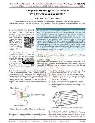
International Journal of Trend in Scientific Research and Development (IJTSRD) Volume: 3 | Issue: 4 | May-Jun 2019 Available Online: www.ijtsrd.com e-ISSN: 2456 - 6470 Compatibility Design of Non-Salient Pole Synchronous Generator Thant Zaw Oo1, Aye Myo Thant2 1Department of Electrical Power Engineering, Technological University, Kalay, Sagaing, Myanmar 2Department of Electrical Power Engineering, Technological University, Mandalay, Mandalay Region, Myanmar How to cite this paper: Thant Zaw Oo | Aye Myo Thant "Compatibility Design of Non-Salient Pole Synchronous Generator" Published in International Journal of Trend in Scientific Research and Development (ijtsrd), ISSN: 2456- 6470, Volume-3 | Issue-4, June 2019, pp.991-994, URL: https://www.ijtsrd.c om/papers/ijtsrd24 026.pdf Copyright © 2019 by author(s) and International Journal of Trend in Scientific Research and Development Journal. This is an Open Access article distributed under the terms of the Creative Commons Attribution License (CC BY 4.0) (http://creativecommons.org/licenses/ by/4.0) The rotor and stator are the rotating and the stationary part of the synchronous generator. They are the power generator components of the synchronous generator. The rotor has the field pole, and the stator consist the armature conductor. The relative motion between the rotor and the stator induces the voltage between the conductors [1].the principle of Faraday’s laws of electromagnetic induction are conducted in that operation. ABSTRACT This paper is focused design calculation of 30 MVA, 11 kV, 50 Hz, two pole (non- salient poles) synchronous generator that use in gas turbine power plant. The choices of specific loadings are magnetic loading and electric loading are involved in that design calculation. The number of rotor slot selection main considered in order to avoid the undesirable effects of harmonics in the flux density wave forms. The rotors are cylindrical in shape having parallel slots on it to place rotor windings. The design system is compatibility based on where specific magnetic loading or specific electric loading with synchronous generator generate more electrical power and to get better performance. The relation between specific loading and volume of the generator, short circuit ratio and air gap length, comparison design data and efficiency due to load changing are mainly emphasized studying in this paper. Keywords: synchronous generator, reactive power, air gap length, load changing, non-salient pole 1.INTRODUCTION The electromagnetic induction states that electromotive force induced in the armature coil if it is rotating in the uniform magnetic field. The E.M.F will also be generated if the field rotates and the conductor becomes stationary. The wave shape of induces voltage always a sinusoidal curve. IJTSRD24026 figure 2. The following parameters are advantages things that are forced to apply in gas turbine application. A.smaller in diameter but having longer axial length. B.cylindrical rotors are used in high speed electrical machines, in this paper, 3000 rpm and number of pole are two pole are focused. C.noise of winding loss is less construction is robust. D.damper windings are not needed in that rotors. E.this rotor synchronous generator is used in gas power plants. Figure 2.Non- Salient Pole Rotor(Cylindrical rotor) Figure1. Construction of Non-Salient Pole Synchronous Generator 2.COMPATIBILITY DESIGN CONSIDERATION The non salient-pole synchronous machines are designed to achieve the following information’s regarding its various parts to supply these data to the manufacture. The main These rotors are cylindrical in shape having parallel slots on it to place rotor windings. It is made up of solid steel in @ IJTSRD | Unique Paper ID – IJTSRD24026 | Volume – 3 | Issue – 4 | May-Jun 2019 Page: 191
International Journal of Trend in Scientific Research and Development (IJTSRD) @ www.ijtsrd.com eISSN: 2456-6470 consideration facts are dimensions of stator frame, complete details of the stator winding, details of the rotor and its winding and performance of the designed parts, in order to justify the design of the above parts in order to lower cost, small size and lower weight. The load varies in lagging or leading effect with the stability of field excitation in constant voltage. The figure (1) shows the field current required maintaining rated terminal voltage as the constant power factor load is varied. The maximum apparent power load at a specific voltage and rated power factor (lagging) which they can carry continuously without overheating. The terminal voltage which related to field current at constant level operation is within less or more five percent. In order to maintain real power and voltage, the reactive power is controlled with field winding heating. Average loss factor, 2 m = 1 + ( αh )4 (4) c 9 copper width in the slot α = (5) slot width where, hc = depth of the strand or conductor m = number of conductors in the slot depth Eddy current losses = (Kdav– 1) copper losses in stator winding Stray load losses for the alternator may be taken approximately 15 of the total copper losses and eddy current losses[5]. ltage exciter vo 0.85) to (0.8 Vc= (6) number of field coils Where, Vc= Voltage per coil Length of the turn, Lmt= (2L + 1.8 Sectional area of field conductor, ( f f mt V The effective generated voltage per phase is the sum of the no load voltage and the armature reaction emf [5]. Eegp = Eo + Ear =Vt +Ra jXa (9) where, Eegp = effective generated voltage per phase, VT = Terminal voltage per phase, Ra = Armature resistance per phase, Xa = Armature reactance per phase, The armature reaction induced voltage per phase is given by: Ear = −jIaXm Where, Ia is the armature current per phase The no-load induced electromotive force Eo= Vt +jIaZs The synchronous impedance Zs= Ra+ jXs pτ + 0.25) m (7) ) ρL I T af = (8) c Figure3. Characteristic form of SynchronousGenerator Compound Curve [5] 2.1.Mathematical Review The equivalent circuit of the stator and the cylindrical rotor of the non-salient pole of the synchronous generator relation are shown in figure (4). The volume of the machine (D2L) is reduced, if designed for higher speed, thus decreasing the size and the cost of the machine that express in equation (1) derivation. If machine is designed at higher specific magnetic and electric loadings, output coefficient is larger, which ultimately results into the reduction of size and cost of the machine. The generation driven is shown in capability diagram in figure (4) in which apparent power in generator operation with constant excitation; the electromagnetic voltage induced from terminal voltage and reactance with the concern of loss for lagging condtion while load condition is running in stability limit with the power angle, δ and ɸ, etc. A.Watts radiated from the field coil = External surface in cm2 x watts/cm2 (1) = External periphery of the field coil x Height of the field coil x watts/cm2 (2) B.Specific electric loading, Q = (11×Bavqkw×10-3) D2Lns (3) Where, Bav = Average flux density in the air gap, Tesla Kw = Stator winding factor Ns = Speed of the machine, rps D = Internal diameter of stator, meter L = Gross length of stator, meter (10) (11) (5) Figure4. Capability Curve of Salient Pole Synchronous Generator @ IJTSRD | Unique Paper ID – IJTSRD24026 | Volume – 3 | Issue – 4 | May-Jun 2019 Page: 992
International Journal of Trend in Scientific Research and Development (IJTSRD) @ www.ijtsrd.com eISSN: 2456-6470 3.RESULTS DATA OF CACULATION The insulation system for low voltage machines presents no particular difficulty, because insulation which is strong enough mechanically is sufficient for electrical purposes. However, the thickness of insulation required is quite large for high voltage alternators, in order to prevent the breakdown of insulation system [3]. Table 1.Thickness of Stator Winding Insulation Voltage (kV) 5 (Bitumen mica folium insulation) (Epoxy Novalak mica-paper) 3.1.The Relation of Specific Electric Loading and Voltage In the design of synchronous generator, specific loading are very important for output equation, which is basic tool in designing. So, the specific loadings are attentively chosen. The specific loading is the average of the magnitude of the radial flux density over the entire cylindrical surface of the rotor. In order to calculate the diameter and length of rotor, mean flux density to get the optimal design. The following curve is obtained by using the output rating and output coefficient equations and assuming the constant 0.67 Tesla of specific magnetic loading (Bav) to get the desired design. The relation between specific electric loadings and volume of the generator is shown in Figure 4.2 and Table 4.3. 10 11 12 14 16 2.6 3.6 3.8 4.1 4.6 5.1 2.1 3.0 3.2 3.4 3.8 4.2 Figure6. Short Circuit Ratio and Air Gap Length 3.3.Efficiency due to Load Changing Efficiency refers to very different inputs and outputs in different fields and industries. Efficiency is very often confused with effectiveness. Figure 4. represent the efficiency due to load changing. In this thesis, the generator has been designed to get the maximum efficiency in 30 MVA rating. The following are the comparison between previous design data of 25.25 MVA synchronous generator[2] and calculated design data of 30MVA synchronous generator. Due to the choosing of larger specific loading in the design, the diameter and length of the generator are reduced to 86cm and 196cm from 250 cm and 620 cm respectively. Although the number of stator slots is 30 slots [2], now, it is chosen 48 slots to reduce the reactance in this design. The more space between the conductors for circulation of air, the lower internal temperature and the better cooling system. Moreover, the conductors in windings are stranded into strands. The eddy current loss in one strand cannot share to the other strand. So, the eddy current losses can be reduced. Because of the reduction of the losses of the generator, the efficiency is better from 89.6% in 25.25 MVA to 97.28% in 30 MVA. Therefore, this generator design is satisfactory not only to produce bulk power, but also efficiency and size of generator. Figure5. Relation of Specific Electric Loading and Voltage 3.2.The Relation between Short Circuit Ratio and Air Gap Length The air gap length in synchronous generator is an important design parameter because its value greatly influences the performance of the generator. However, it can be seen that the value of air gap length is directly proportional to the short circuit ratio. Short circuit ratio is an important factor of the synchronous machine. It affects the operating characteristics, physical size and cost of the machine. The large variation in the terminal voltage with a change in load takes place for the lower value of the short circuit ration of a synchronous generator. In this design, SCR is attentively chosen to get desired value of air gap length. The short circuit ratio is directly proportional to the air gap reluctance or air gap length. Table 2 and Figure 3 show the relation between short circuit ratio and air gap length. Figure7. Efficiency due to load changing 4.CONCLUSIONS To carry out the design for obtaining the above information, the following factors are considerate and calculated. There are; detailed specifications, design equation based on which the design is initiated, proper information for choosing justified values of various design parameters, such as specific magnetic loading, specific electric loading etc. and also knowledge of available materials, magnetic, insulating, conducting and their typical behavior, limiting values of various performance parameters, such as iron losses, @ IJTSRD | Unique Paper ID – IJTSRD24026 | Volume – 3 | Issue – 4 | May-Jun 2019 Page: 993
International Journal of Trend in Scientific Research and Development (IJTSRD) @ www.ijtsrd.com eISSN: 2456-6470 [2]Caterpillar, “Generator System, Application and Industrial Guide”, 2008 efficiency, short circuit current, etc are considered based load on 30MVA assume in gas turbine application in which non salient pole type synchronous generator preferred for large load. 5.ACKNOWLEDGEMENTS The author is deeply grateful to his teachers who are working in Electrical Power Engineering Department, Technological University (Kalay) for their willingness to share of ideas and helpful suggestions on this paper writing. 6. REFERENCES [1]Tze Fun Chan, “Synchronous Machine, Polytechnic University, Hong Kong, 2003 [3] Smith, “Motors and Generators for Micro-hydropower, Intermediate Technology Publications, London, 1994 [4]Yahaya Asizehi ENESI*, Adamu Murtala ZUNGERU, Isah Agbogunde ADEMOH, “Analysis of Non-Salient Pole Synchronous Generator Using Phasor Diagrams”, Department of Electrical and Electronics Engineering, Federal University of Technology, PMB 65, Minna, Niger state, Nigeria, 2014. [5] B.R. Gupta Bandana Singhal, “Fundamental of Electric Machines” Reversed Third Edition, 2010 @ IJTSRD | Unique Paper ID – IJTSRD24026 | Volume – 3 | Issue – 4 | May-Jun 2019 Page: 994