Download
1 / 5
50 likes | 80 Views
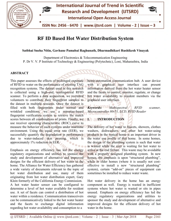
This paper assesses the effects of prolonged exposure of RFID to water on the performance of existing TAG recognition systems. The dataset used in this research is collected using a high end, multispectral RFID scanner. To perform a data acquisition, we recruited volunteers to contribute their fingerprint samples to the dataset in multiple sessions. Once the dataset is filled with both fingerprints under normal and wrinkled conditions, we use a minutiae based fingerprint verification system to retrieve the match scores between all combinations of prints. Finally, we use receiver operating characteristic ROC curve to measure the behavior of such systems under maritime environment. Using the equal error rate EER , we successfully quantify the degradation in performance due to water induced skin pruning, which is approximately 1 reduction in EER. Emphasis on energy efficiency has led the energy regulatory organizations and utilities to sponsor the study and development of alternative and improved designs for the efficient delivery of hot water in the home. The Alliance for Water Efficiency has gathered a wide variety of documents relevant to the topic of hot water distribution and use, many of them originating from hot water distribution expert, Gary Klein formerly of the California Energy Commission. A hot water heater sensor can be configured to determine a level of hot water available for resident use. A set of facets can control a distribution of hot water within a residence. Communication transceivers can be communicatively linked to the hot water heater and the facets to exchange digital information regarding hot water availability and consumption to a home automation communication hub. A user device with a graphical user interface can present information derived from the hot water heater sensor and the facets to control, monitor, regulate, or change hot water availability to resident members via the graphical user interface. Satbhai Sneha Nitin | Gavhane Pamabai Raghunath | Dharmadhikari Rushikesh Vinayak "RF ID Based Hot Water Distribution System" Published in International Journal of Trend in Scientific Research and Development (ijtsrd), ISSN: 2456-6470, Volume-2 | Issue-3 , April 2018, URL: https://www.ijtsrd.com/papers/ijtsrd12715.pdf Paper URL: http://www.ijtsrd.com/engineering/electronics-and-communication-engineering/12715/rf-id-based-hot-water-distribution-system/satbhai-sneha-nitin<br>

E N D
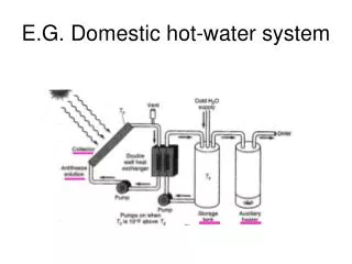
International Research Research and Development (IJTSRD) International Open Access Journal RF ID Based Hot Water Distribution System Gavhane Pamabai Raghunath, Dharmadhikari Rushikesh International Journal of Trend in Scientific Scientific (IJTSRD) International Open Access Journal ISSN No: 2456 ISSN No: 2456 - 6470 | www.ijtsrd.com | Volume 6470 | www.ijtsrd.com | Volume - 2 | Issue – 3 RF ID Based Hot ater Distribution System Satbhai Sneha Nitin, Gavhane Rushikesh Vinayak Department of Electronics & Department of Electronics & Telecommunication Engineering P. Dr V. V. P Institute of Technology & Engineering (Polytechnic), Loni, Maharashtra, P. Dr V. V. P Institute of Technology & Engineering (Polytechnic), Loni, Maharashtra, India P. Dr V. V. P Institute of Technology & Engineering (Polytechnic), Loni, Maharashtra, home-automation communication hub. A user device with a graphical user interface can present information derived from the hot water heater sensor and the facets to control, monitor, regulate, or change hot water availability to resident members via the graphical user interface. Keywords: Multispectral Microcontroller 80v51, LCD, RFID Reader I. INTRODUCTION The delivery of hot water to faucets, showers, clothes washers, dishwashers, and other hot water products in the typical home is an important driver in the water use profile of that home. the design of the plumbing system is such that water is wasted while the user is waiting for hot water to arrive at the end fixture. This waste m with a properly designed plumbing system. homes, the emphasis is upon “structured plumbing”, while in older homes (where it is usually not cost effective to install a new “structured plumbing” system), certain “add-on” pieces of equ sometimes be installed to reduce water waste. Hot water delivery in the home has an energy component as well. Energy is wasted in inefficient systems where hot water is wasted or sits in pipes unused. Emphasis on energy efficiency has led the energy regulatory organizations and utilities to sponsor the study and development of alternative and improved designs for the efficient delivery of hot water in the home. ABSTRACT This paper assesses the effects of prolonged exposure of RFID to water on the performance of existing TAG recognition systems. The dataset used in this research is collected using a high-end, multispectral RFID scanner. To perform a data acquisition, we recruited volunteers to contribute their fingerprint samples to the dataset in multiple sessions. Once the dataset is filled with both fingerprints under normal and wrinkled conditions, we use a minutiae fingerprint verification system to retrieve the match scores between all combinations of prints. Finally, we use receiver operating characteristic (ROC) curve to measure the behavior of such systems under maritime environment. Using the equal error rate (EER), we successfully quantify the degradation in performance due to water-induced skin pruning, which is approximately 1% reduction in EER. Emphasis on energy efficiency has led the energy regulatory organizations and utilities to sponsor the study and development of alternative and improved designs for the efficient delivery of hot water in the home. The Alliance for Water Efficiency has gathered a wide variety of documents relevant to the topic of hot water distribution and use, many of them originating from hot water distribution expert, Gary Klein formerly of the California Energy Commission. A hot water heater sensor can be configured to determine a level of hot water available for resident use. A set of facets can control a distribution of hot water within a residence. Communication transceivers can be communicatively linked to the hot water heater and the facets to exchange digital information regarding hot water availability and consumption to a availability and consumption to a This paper assesses the effects of prolonged exposure of RFID to water on the performance of existing TAG systems. The dataset used in this research automation communication hub. A user device with a graphical user interface can present information derived from the hot water heater sensor and the facets to control, monitor, regulate, or change ability to resident members via the end, multispectral RFID scanner. To perform a data acquisition, we recruited volunteers to contribute their fingerprint samples to the dataset in multiple sessions. Once the dataset is lled with both fingerprints under normal and wrinkled conditions, we use a minutiae-based fingerprint verification system to retrieve the match scores between all combinations of prints. Finally, we use receiver operating characteristic (ROC) curve to ure the behavior of such systems under maritime environment. Using the equal error rate (EER), we successfully quantify the degradation in performance induced skin pruning, which is Multispectral RFID RFID scanner, scanner, Microcontroller 80v51, LCD, RFID Reader The delivery of hot water to faucets, showers, clothes washers, dishwashers, and other hot water-using products in the typical home is an important driver in the water use profile of that home. In some homes, the design of the plumbing system is such that water is wasted while the user is waiting for hot water to This waste may be avoidable with a properly designed plumbing system. In new homes, the emphasis is upon “structured plumbing”, while in older homes (where it is usually not cost- effective to install a new “structured plumbing” on” pieces of equipment can sometimes be installed to reduce water waste. ency has led the energy regulatory organizations and utilities to sponsor the study and development of alternative and improved designs for the efficient delivery of hot water in the home. The Alliance for Water Efficiency has gathered cuments relevant to the topic of hot water distribution and use, many of them originating from hot water distribution expert, Gary Klein formerly of the California Energy Commission. A hot water heater sensor can be configured to Hot water delivery in the home has an energy Energy is wasted in inefficient systems where hot water is wasted or sits in pipes Emphasis on energy efficiency has led the energy regulatory organizations and utilities to sponsor the study and development of alternative and improved designs for the efficient delivery of hot ater available for resident use. A set of facets can control a distribution of hot water within a residence. Communication transceivers can be communicatively linked to the hot water heater and the facets to exchange digital information @ IJTSRD | Available Online @ www.ijtsrd.com @ IJTSRD | Available Online @ www.ijtsrd.com | Volume – 2 | Issue – 3 | Mar-Apr 2018 Apr 2018 Page: 2161
International Journal of Trend in Scientific Research and Development (IJTSRD) ISSN: 2456-6470 The Alliance for Water Efficiency has gathered a wide variety of documents relevant to the topic of hot water distribution and use, many of them originating from hot water distribution expert, Gary Klein formerly of the California Energy Commission. Enormous growth of residential areas has led to over demand of water to fulfill daily activities. Without water nothing happens in any kind of environment. Importance of water is realized only when it is not available. People utilize water for many purposes and consume them by different ways. But there are many issues which arise when they consume in high amount. That is termed as water theft. It leads to scarcity of water in some areas. Among a particular water distribution unit problem arises between consuming units because of water theft. Also many problems occur when supplied water is in lack of quality because of leakage in pipelines or by contamination because of harmful organisms. To overcome those issues proposed system consists of flow monitoring system, quality assurance system and automated supply system. Such an integrating system is capable of predicting flow of water, issuable of water with appreciable quality and automatic supply of water. It can be done by employing sensors such as flow sensors and turbidity sensors. Automatic supply acts as solution for the need of experienced operators and wastage of water during supply. II. BLOCK DIAGRAM – MICROCONTROLLER: In 1981, Intel Corporation introduced an 8 bit microcontroller called 8051. This microcontroller contains 128 bytes of RAM, 4K bytes of on-chip ROM, two timers, one serial port and four ports(each 8 bits wide) all on a single chip. The 8051 is an 8-bit processor, meaning that the CPU can work on only 8 bits of data at a time. Although the 8051 can have a maximum of 64K bytes of on-chip ROM, many manufacturers have put only 4K bytes on the chip. There are many flavors of 8051 which different speeds and amounts of on-chip ROM. 8051 is available in different memory types such as UV- EPROM, flash and microcontrollers are high-performance static 80V51 designs. They are manufactured in an advanced CMOS process and contain a non-volatile Flash program memory that is programmable in parallel (via a parallel programmer) or In-System Programmable (ISP) via boot loader. They support both 12-clock and 6-clock operation. AT89C51 contain 1024 bytes RAM, 32 I/O lines, three 16-bit counter/timers, a six- source, four-priority level nested interrupt structure, a serial I/O port for communications, I/O expansion or full duplex UART, and on-chip oscillator and clock circuits. As we all know that computer can only understands the machine language which is consist of 0’s and 1’s and it is cumbersome and difficult to write the program in 0’s and 1’s. So, to make it easy for the users, the assembler was introduced. The assembler is software which translates the assembly language into machine language. Assembly language contains mnemonics for machine code instructions plus other more features that makes programming faster and less prone to error. POWER SUPPLY: When working with electronics, you always need one basic thing: Power. In every electronic circuit power supply is required. The proper working of each and every component, the exact amount of voltage and current to be supplied to it. If the power exceed its limit, it can be fatal. Bridge Rectifier: A bridge rectifier can be made using four individual diodes, but it is also available in special packages containing the four diodes required. It is called a full- wave rectifier because it uses all the AC wave (both NVRAM. The Atmel either multi-processor Block Diagram Description- @ IJTSRD | Available Online @ www.ijtsrd.com | Volume – 2 | Issue – 3 | Mar-Apr 2018 Page: 2162
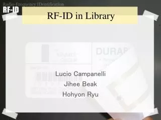
International Journal of Trend in Scientific Research and Development (IJTSRD) ISSN: 2456-6470 positive and negative sections). 1.4V is used up in the bridge rectifier because each diode uses 0.7V when conducting and there are always two diodes conducting, as shown in the diagram below. Bridge rectifiers are rated by the maximum current they can pass and the maximum reverse voltage they can withstand (this must be at least three times the supply RMS voltage so the rectifier can withstand the peak voltages LCD- The three control lines are EN, RS, and RW. The EN line is called "Enable." This control line is used to tell the LCD that you are sending it data. To send data to the LCD, your program should make sure this line is low (0) and then set the other two control lines and/or put data on the data bus. When the other lines are completely ready, bring EN high (1) and wait for the minimum amount of time required by the LCD datasheet (this varies from LCD to LCD), and end by bringing it low (0) again. The RS line is the "Register Select" line. When RS is low (0), the data is to be treated as a command or special instruction (such as clear screen, position cursor, etc.). When RS is high (1), the data being sent is text data which should be displayed on the screen. For example, to display the letter "T" on the screen you would set RS high. The RW line is the "Read/Write" control line. When RW is low (0), the information on the data bus is being written to the LCD. When RW is high (1), the program is effectively querying (or reading) the LCD. Only one instruction ("Get LCD status") is a read command. All others are write commands--so RW will almost always be low. Finally, the data bus consists of 4 or 8 lines (depending on the mode of operation selected by the user). In the case of an 8-bit data bus, the lines are referred to as DB0, DB1, DB2, DB3, DB4, DB5, DB6, and DB7. Liquid Crystal Display also called as LCD is very helpful in providing user interface as well as for debugging purpose. The most common type of LCD controller is HITACHI 44780 which provides a simple interface between the controller & an LCD. These LCD's are very simple to interface with the controller as well as are cost effective. The most commonly used ALPHANUMERICdisplays are 1x16 (Single Line & 16 characters), 2x16 (Double Line & 16 character per line) &4x20(four lines & Twenty characters per line). The LCD requires 3 control lines (RS, R/W & EN) & 8 (or 4) data lines. The number on data lines depends on the mode of operation. If operated in 8-bit mode then 8 data lines + 3 control lines i.e. total 11 lines are required. And if operated in 4-bit mode then 4 data lines + 3 control lines i.e. 7 lines are required. How do we decide which mode to use? It’s simple if you have sufficient data lines you can go for 8 bit mode & if there is a time constrain i.e. display should be faster then we have to use 8-bit mode because basically 4- bit mode takes twice as more time as compared to 8- bit mode. When RS is low (0), the data is to be treated as a command. When RS is high (1), the data being sent is considered as text data which should be displayed on the screen. When R/W is low (0), the information on the data bus is being written to the LCD. When RW is high (1), the program is effectively reading from the LCD. Most of the times there is no need to read from the LCD so this line can directly be connected to Gnd thus saving one controller line. The ENABLE pin is used to latch the data present on the data pins. A HIGH - LOW signal is required to latch the data. The LCD interprets and executes our command at the instant the EN line is brought low. If you never bring EN low, your instruction will never be executed. RFID- RFID is an acronym identification. Briefly the RF stand for “radio- frequency” and ID means “identifier” that allows an item, for instance a library book, to be identified, accessed, stored, reprogrammed and communicated by using radio waves RADIO FREQUENCY (RFID) is a generic term for non-contacting technologies that use radio waves to automatically identify people or objects. There are several methods of identification, but the most common is to store a unique serial number that identifies a person or object on a microchip that is attached to an antenna. The for radio frequency IDENTIFICATION- @ IJTSRD | Available Online @ www.ijtsrd.com | Volume – 2 | Issue – 3 | Mar-Apr 2018 Page: 2163
International Journal of Trend in Scientific Research and Development (IJTSRD) ISSN: 2456-6470 combined antenna and microchip are called an "RFID transponder" or "RFID tag" and work in combination with an "RFID reader" (sometimes called an "RFID interrogator"). An RFID system consists of a reader and one or more tags. The reader's antenna is used to transmit radio frequency (RF) energy. Depending on the tag type, the energy is "harvested" by the tag's antenna and used to power up the internal circuitry of the tag. The tag will then modulate the electromagnetic waves generated by the reader in order to transmit its data back to the reader. The reader receives the modulated waves and converts them into digital data. There are two major types of tag technologies. "Passive tags" are tags that do not contain their own power source or transmitter. When radio waves from the reader reach the chip’s antenna, the energy is converted by the antenna into electricity that can power up the microchip in the tag (known as "parasitic power"). The tag is then able to send back any information stored on the tag by reflecting the electromagnetic waves as described above. "Active tags" have their own power source and transmitter. The power source, usually a battery, is used to run the microchip's circuitry and to broadcast a signal to a reader. Due to the fact that passive tags do not have their own transmitter and must reflect their signal to the reader, the reading distance is much shorter than with active tags. However, active tags are typically larger, more expensive, and require occasional service. The Sunrom RFID Card Reader is designed specifically for passive tags. Frequency refers to the size of the radio waves used to communicate between the RFID system components. Just as you tune your radio to different frequencies in order to hear different radio stations, RFID tags and readers must be tuned to the same frequency in order to communicate effectively. There really is no such thing as a "typical" RFID tag. The read range of a tag ultimately depends on many factors: the frequency of RFID system operation, the power of the reader, environmental conditions, physical size of the tags antenna and interference from other RF devices. Balancing a number of engineering trade-offs (antenna size v. reading distance v. power v. manufacturing cost),the Sunrom RFID Card Reader's antenna was designed with a RFID operation at a tag read distance of around 7 cm. RFID READER: RADIO (RFID) Card Readers provide a low-cost solution to read passive RFID transponder tags up to 7 cm away. This RFID Card Reader can be used in a wide variety of hobbyist and commercial applications, including access control, automatic identification, robotics navigation, inventory tracking, payment systems, and car immobilization. The RFID card reader read the RFID tag in range and outputs unique identification code of the tag at baud rate of 9600. The data from RFID reader can be interfaced to be read by microcontroller or PC. FLOWCHART: FREQUENCY IDENTIFICATION ADVANTAGES Reduced Fuel Expenses Improved Customer Service Updates screen every second with new data It has more accuracy. NOT Expensive. @ IJTSRD | Available Online @ www.ijtsrd.com | Volume – 2 | Issue – 3 | Mar-Apr 2018 Page: 2164
International Journal of Trend in Scientific Research and Development (IJTSRD) ISSN: 2456-6470 reduction in water-borne illnesses, and increase in usable time daily. This will lead to the citizens moving toward prosperity and naturally evolving economic opportunities. An immediate economic impact will be the creation of jobs involving the maintenance of the system. REFERENCES 1.American Water Works Association (AWWA). 2001. Reinvesting in drinking water structure: dawn of the replacement era. Denver, CO: AWWA. APPLICATION: The proposed system can be used for hot water distribution management The proposed system can be used for municipality water distribution management The system can be used in village water distribution management. Result: A)Project Model 2.AWWA. 2003. Water Stats 2002 Distribution Survey CD-ROM. Denver, CO: AWWA. 3.AWWA and EES, Inc. 2002a. Permeation and leaching. Available http://www.epa.gov/safewater/tcr/pdf/permleach.p df. Accessed March 16, 2005. on-line at 4.AWWA and EES, Inc. 2002b. Effects of water age on distribution system water quality. http://www.epa.gov/safewater/tcr/pdf/waterage.pd f. Accessed March 16, 2005. 5.AWWA and EES, Inc. 2002c. Finished water storage facilities. http://www.epa.gov/safewater/tcr/pdf/storage.pdf. Accessed March 16, 2005. Available on-line at B) Displayed Massage 6.AWWA and EES, Inc. 2002d. Nitrification. Available http://www.epa.gov/safewater/tcr/pdf/nitrification. pdf. Accessed March 16, 2005. on-line at CONCLUSION One of the obvious direct benefits of this paper is potable water for a large group of people, in a country where potable water is the exception rather than the norm. Having quick and easy access to potable water will lead to a variety of vast improvements in the quality of life, such as increased life expectancy, @ IJTSRD | Available Online @ www.ijtsrd.com | Volume – 2 | Issue – 3 | Mar-Apr 2018 Page: 2165