Download
1 / 4
60 likes | 92 Views
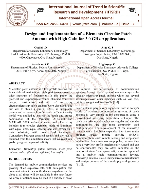
Microstrip patch antenna is a low profile antenna that is capable of maintaining high performance over a wide spectrum of frequencies. In this paper the practical and experimental results obtained from the design, construction and test of an array circularmicrostrip patch antenna were discussed. The aim was to obtain a gain of 12dB, an acceptable pattern and a reasonable reflection coefficient cavity model was applied to analyze the patch and proper combination of the formulae ADS2000 and MATLAB 2013 softwares were used. The array includes four circular elements made of aluminum with equal sizes, equal spacing and was grown on a resin substrate, with insect feed techniques. Comparison between practical results and the results obtained from the simulation shows that we reach our goals by a great degree of validity. Olabisi .O | Ajao O. S | Adeniran A.O | Adgboyega O. "Design and Implementation of 4 Elements Circular Patch Antenna with High Gain for 3.0 GHz Applications" Published in International Journal of Trend in Scientific Research and Development (ijtsrd), ISSN: 2456-6470, Volume-2 | Issue-2 , February 2018, URL: https://www.ijtsrd.com/papers/ijtsrd9596.pdf Paper URL: http://www.ijtsrd.com/other-scientific-research-area/other/9596/design-and-implementation-of-4-elements-circular-patch-antenna-with-high-gain-for-30-ghz-applications/olabisi-o<br>

E N D
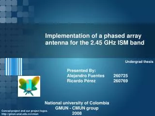
International Research Research and Development (IJTSRD) International Open Access Journal nd Implemantation of 4 Elements Circular Patch ith High Gain for 3.0 GHz Applications International Journal of Trend in Scientific Scientific (IJTSRD) International Open Access Journal ISSN No: 2456 ISSN No: 2456 - 6470 | www.ijtsrd.com | Volume 6470 | www.ijtsrd.com | Volume - 2 | Issue – 2 Design and Implemantation Antenna with High Gain f 4 Elements Circular Patch z Applications Olabisi .O Ajao O. S Ajao O. S Department of Science Laboratory Technology, LadokeAkintola University of Technology, P.M.B 4000, Ogbomoso, Oyo State, Nigeria Adeniran A.O Department of Physics, Federal University of Uyo, P.M.B 1017, Uyo, AkwaIbom State, Nigeria Department of Science Laboratory Technology, LadokeAkintola University of Technology, P.M.B 4000, Ogbomoso, Oyo State, Nigeria Department of Science Laboratory Technology, OkeOgun Polytechnics, P.M.B 021 Saki, Oyo State, Nigeria Adgboyega O. Department of Physics Emmanuel Alayande College of Education Oyo, P.M.B 10 Oyo State, Nigeria Department of Science Laboratory Technology, OkeOgun Polytechnics, P.M.B 021 Saki, Nigeria Adgboyega O. Department of Physics, Federal University of Uyo, AkwaIbom State, Nigeria Department of Physics Emmanuel Alayande College of Education Oyo, P.M.B 1010 Oyo, Nigeria ABSTRACT Microstrip patch antenna is a low profile antenna that is capable of maintaining high performance over a wide spectrum of frequencies. In this paper the practical and experimental results obtained from the design, construction and circularmicrostrip patch antenna were discussed. The aim was to obtain a gain of 12dB, an acce pattern and a reasonable reflection coefficient cavity model was applied to analyze the patch and proper combination of the formulae; ADS2000 and MATLAB 2013 softwares were used. The array includes four circular elements made of aluminum with equal sizes, equal spacing and was grown on a resin substrate, with insect Comparison between practical results and the results obtained from the simulation shows that we reach our goals by a great degree of validity. Keywords: Microstrip patch antenna, inset feed, antenna gain, reflection coefficient, low profile INTRODUCTION Microstrip patch antenna is a low profile antenna that to improve the performance of communication systems. A very popular type of antenna arrays is the circular microstrip patch antenna which has several other schemes such as low cost, to improve the performance of communication systems. A very popular type of antenna arrays is the circular microstrip patch antenna which has several advantages over other schemes such as low cost, minimal weight and low profile [1 minimal weight and low profile [1-5]. performance over a wide spectrum of frequencies. In this paper the practical and experimental results obtained from the design, construction and circularmicrostrip patch antenna were discussed. The aim was to obtain a gain of 12dB, an acceptable pattern and a reasonable reflection coefficient cavity model was applied to analyze the patch and proper combination of the formulae; ADS2000 and MATLAB 2013 softwares were used. The array includes four circular elements made of aluminum sizes, equal spacing and was grown on a resin substrate, with insect feed Comparison between practical results and the results obtained from the simulation shows that we reach our test test of of an an array array Patch antenna play a very significant role in today’s world of wireless communication systems. A patch antenna is very simple in the construction using a fabrication technique. The patch can take any shape but rectangular and circular configurations are the most commonly used configurations. The development of the microstrip patch antenna has been expanded into three major program areas; mobile communication, earth remote sensing and deep-space exploration. Patch antennas are popular, because they have a very low profile mechanically rugged and can be conformable; they are often mounted on the exterior of aircraft and spacecraft, or are incorporated into a mobile radio communications devices. Microstrip antenna is also inexpensive to manufacture and design because of the simple physical geometry Patch antenna play a very significant role in today’s world of wireless communication systems. A patch antenna is very simple in the construction using a conventional microstrip fabrication technique. The patch can take any shape but rectangular and circular configurations are the most commonly used configurations. The development of the microstrip patch antenna has been expanded into three major program areas; mobile communication, earth remote sensing and deep exploration. Patch antennas are popular, because they have a very low profile mechanically rugged and can be conformable; they are often mounted on the exterior of aircraft and spacecraft, or are inco into a mobile radio communications devices. Microstrip antenna is also inexpensive to manufacture and design because of the simple physical geometry [6-10]. feed techniques. techniques. satellite satellite (M (MSAT) antenna, inset feed, ection coefficient, low profile The demand for mobile communication services are growing at an explosive rate, with anticipation that communication to a mobile device anywhere on the globe at all times will be available in the near future. An array of antenna may be used in a variety of ways An array of antenna may be used in a variety of ways The demand for mobile communication services are growing at an explosive rate, with anticipation that communication to a mobile device anywhere on the will be available in the near future. @ IJTSRD | Available Online @ www.ijtsrd.com @ IJTSRD | Available Online @ www.ijtsrd.com | Volume – 2 | Issue – 2 | Jan-Feb 2018 Feb 2018 Page: 996
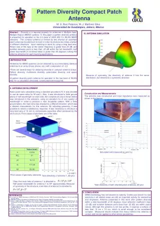
International Journal of Trend in Scientific Research and Development (IJTSRD) ISSN: 2456 International Journal of Trend in Scientific Research and Development (IJTSRD) ISSN: 2456 International Journal of Trend in Scientific Research and Development (IJTSRD) ISSN: 2456-6470 MATERIALS AND METHOD In this paper, an antenna array consisting of four equal circular elements with equal spacing, has been examined. In this paper, an antenna array consisting of four equal elements with equal spacing, has been Thus the effective area of the circular patch element is Thus the effective area of the circular patch element is given by [2] Where ƒr is the resonant frequency in (Hz). The radiated field of the E-plane for a single element circular patch can be expressed by (Alade&Olabisi) circular patch can be expressed by (Alade&Olabisi) Figure 1: Geometry of circular patch antenna 1: Geometry of circular patch antenna is the resonant frequency in (Hz). plane for a single element The resonant frequency of a circular patch can be The resonant frequency of a circular patch can be computed as Figure 2: Geometry of the array of circular microstrip patch elements In Figure 2, the way of arranging cicular patches and feeding is shown the antenna is fed from its center they have the same phase in their entries considering the shapes of feed lines for each of the circular patches. THEORY Figure 2: Geometry of the array of circular In Figure 2, the way of arranging cicular patches and Where ƒo = resonant frequency Jmn =mth zero of the Bessel function or order n RESULT AND DISCUSSION AND DISCUSSION = resonant frequency =mth zero of the Bessel function or order n fed from its center they have the same phase in their entries considering the shapes of feed lines for each of the circular The aim of this work is to develop an antenna with a directional pattern and a gain at least equal to with a directional pattern and a gain at least equal to 12 dB. An antenna array with equal spacing and uniform excitation was designed. The cicularmicrostrip antenna was stimulated by ADS2000 that is based on the method of moment; to obtain pattern for the The aim of this work is to develop an antenna with a directional pattern and a gain at least equal to with a directional pattern and a gain at least equal to 12 dB. An antenna array with equal spacing and uniform excitation was designed. Th antenna was stimulated by ADS2000 that is based on the method of moment; to obtain pattern for the antenna array. In Figure 1, the radius (a) of the circular patch is 2 cm. the height of the substrate (h) is 0.2mm. The dielectric constant (??) is 4.5. From [1] the first order approximation of the physical radius of the circular patches elements. In Figure 1, the radius (a) of the circular patch is 2 cm. the height of the substrate (h) is 0.2mm. The From [1] the first order approximation of the physical In this paper, it is considered that the substrate In this paper, it is considered that the substrate permittivity of the antenna is ?? 0.2mm and the resonance frequency of 3 GHz. the resonance frequency of 3 GHz. ??= 4.5. (resin) height is Figure 3: 3 3-D Radiation Pattern 4x1 Antenna Array @ IJTSRD | Available Online @ www.ijtsrd.com @ IJTSRD | Available Online @ www.ijtsrd.com | Volume – 2 | Issue – 2 | Jan-Feb 2018 Feb 2018 Page: 997
International Journal of Trend in Scientific Research and Development (IJTSRD) ISSN: 2456-6470 Figure 4: The input reflection coefficient of the circular patch microstrip array antenna Figure 5: the Gain The reflection coefficient is not really perfect but it could be used and the gain is negative but radiated power is perfect which gives it advantage over the gain .the antenna was simulated on ADS2000 and frequency range of 5 GHz. The array was constructed as shown in Figure the dimension and structural diagram of the antenna are shown in this figure too. The fabricated patch was designed to operate at 3 GHz. The patch is probe feeding and the ground plane is finite for this patch and has dimensions of 15 by 4cm. by selecting proper values of microstrip line width the length and the position of the feed point, a good impedance matching can be obtained. An inset feed scheme is employed to match the patch antenna to a 50 Ω coaxial probe feed. The dielectric material has a permittivity of 4.5 and a thickness of 0.2mm. The substrate of the antenna is made of resin. Figure 6: Front view of 4 elements microstrip patch antenna Figure 7: Back view of 4 elements microstrip patch antenna @ IJTSRD | Available Online @ www.ijtsrd.com | Volume – 2 | Issue – 2 | Jan-Feb 2018 Page: 998
International Journal of Trend in Scientific Research and Development (IJTSRD) ISSN: 2456-6470 In the practical test carried out by GSP730 spectrum analyser, the value of VSWR in central frequency was 1.5433 that was well in agreement with the theoretical analysis (figure) variation performance is mainly due to imprecise fabrication by a milling machine. The spectrum analyser should be calibrated for a suitable frequency range containing the band where the antenna will operate. (Figures) Conclusion Implementation”. International Journal of research and review of applied sciences, 8 171-187, 2011. 6.Li.X and Liao.J.,” Eye-shaped segmented Reader Antenna for Near-field UHF RFID Applications‟, Progress in Electromagnetic Research.114: 481- 493, 2011. in the measured 7.Anitha V. R and Narayana R. S.”Design of an 8X1 square Microstrip patch Antenna Array”, International journal of Electronic Engineering research 1 (1): 71-77, 2009. A small microstrip patch antenna has been presented. The antenna has been designed to be used in WLAN, WIMAX, applications in the c-band. In fact this antenna was designed for 3GHz and 12dB gain. The antenna has good pattern and proper VSWR at 3GHz. The design has been commercially available ADS 2000, MATLAB 2013 softwares. The design antenna has shown good performance in terms of return losses and radiation (a prototype has been fabricated and tested) good agreement has been obtained between simulation and experimental results, providing validation of the design procedure. Good performance has been obtained for the envisaged applications 8.Mohamed .S and Noha .H.,”A novel internal Dual-polarized EBG Antenna for indoor reception of UHF Terrestial Digital TV Broadcasting‟, International journal of microwave science and technology, 2012:1155-2012, 2012. accomplished using 9.Ollikainen.J and Vainikainen .P.”Radiation and Bandwidth characteristics of two planar multistrip Antennas for mobile communication systems‟, Vehicular Technology Ontario, Canada, 2:1186-1190, 1998. conference, Ottawa, References 1.Ogherohwo E.P, Adeniran A.O, and Olabisi O.(2012) “A study of 300, 600, 900 scalene Triangular patch Antenna (TPA) at 900MHZ” International Journal of Research and Reviews in Applied Sciences, .com,13(2):658-664. www.apparpress 2.AladeM.O,Olabisi.O.(2013)“ Microstrip Patch as Antenna for Terrestrial indoor TV reception” International Journal of Research in Electrical and instrumentation www.ijareeie.com, 2(6):2727-2735. Development of Engineering, 3.Jeng B.M Lee.C.M and Luo C.H., “Multiple – ring monopole Antenna with sleeve – shaped ground for DVB – T Application‟‟, Progress in Electromagnetic research.14:155-161, 2010. 4.Karim M.N.A, Rahim M.K.A, Majid H.A, Ayop. O, Abu M. and ZubirF.”Log periodic fractal Koch Antenna Applications”,Progress research.100:201-218, 2010. for UHF Electromagnetic Band in 5.Kwaha B.J, Inyang O. N &Amalu.P.”The circular microstrip patch antenna – Design and @ IJTSRD | Available Online @ www.ijtsrd.com | Volume – 2 | Issue – 2 | Jan-Feb 2018 Page: 999