Download
1 / 25
260 likes | 432 Views
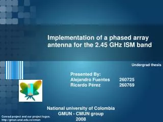
Implementation of a phased array antenna for the 2.45 GHz ISM band. Presented By: Alejandro Fuentes 260725 Ricardo Pérez 260769. Undergrad thesis. National university of Colombia GMUN - CMUN group 2008. Conrad project and our project logos. http://gmun.unal.edu.co/cmun.

E N D
Implementation of a phased array antenna for the 2.45 GHz ISM band Presented By: Alejandro Fuentes 260725 Ricardo Pérez 260769 Undergrad thesis National university of Colombia GMUN - CMUN group 2008 Conrad project and our project logos. http://gmun.unal.edu.co/cmun
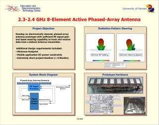
Phased array antenna Passive paa, 2.45 GHz ISM band • Directivity = 8 dB • Scanning (main lobe rotation)= ± 10º • Build prototype • Characterize prototype Source: [1] UNAL 2008 Page 2
Phaseshifters UNAL 2008 Page 3
Overview • Objetive: change phase angle of main lobe from a radiation pattern. • Analog and digital devices. Source: [2] UNAL 2008 Page 4
Types • Diode phase shifters • Ferrite phase shifters • RF MEMS phase shifters UNAL 2008 Page 5
Diode phase shifters Main idea: choice among two lenghts of transmission lines. Source: [3] UNAL 2008 Page 6
Diode phase shifters Circuits Hybrid circuit • Uses balanced reflecting circuits at the output arms of a 3 dB at 90°. Source: [3] Loaded line circuit • Transmission lines spaced λ/4 for keeping coupled input Source: [3] UNAL 2008 Page 7
Diode phase shifters Important aspects • Works satisfactorily below 2 GHz. • Certain applications required carefully design in dc bias. • Can handle tens of watts of RF power. UNAL 2008 Page 8
Ferrite phase shifters • Most popular for controling high power radar arrays. • Several switching speeds. • Works near saturated state. • Phase bits are determined by the length of the toroid • Airborne systems. Source: [3] UNAL 2008 Page 9
RF MEMS phase shifters • Hybrid combination (RF MEMS switches and transmission lines) • Circuits are similar to diode phase shifters circuits. • Satisfactory performing in the large arrays. Source: [4] UNAL 2008 Page 10
RF MEMS phase shifters Circuits Reflection transmission line • Consists of a three port device, a variable length transmission line, and a short. Source: [3] Capacitively loaded line • Changes capacitance changes the line impedance and phase. Source: [3] UNAL 2008 Page 11
Feed Networks UNAL 2008 Page 12
Source: [4] Parallel and series feed systems It is refered to geometry. Each one has advantages and disadvantages to be monitored UNAL 2008 Page 13
Feed Networks Parallel • Symmetrical configuration. • Asymmetrical configuration. Advantages: Powerdistribution. Disadvantages: Long transmissionlines, highinsertionloss. Source: [5] UNAL 2008 Page 14
Feed Networks Parallel One dimension Source: [5] UNAL 2008 Page 15
Feed Networks Parallel Two dimensions Source: [5] Designing on a thin substrate and high frecuencies. UNAL 2008 Page 16
Feed Networks Series • Untransposedconfiguration. • Transposedconfiguration. Advantages: Fewtransmissionlines. Disadvantages: Narrowbandwidth, beamshiftwithfrecuencies. Source: [5] UNAL 2008 Page 17
Pattern Control UNAL 2008 Page 18
Pattern control Distributions • Taylor distribution • Dolph-Chevyshev distribution • Bayliss Difference distribution • Binomial array distribution Source: [2] UNAL 2008 Page 19
Taylor distribution Source: [2] UNAL 2008 Page 20
Dolph-Chevyshev distribution Maximun directivity if the sidelobes level is equal for each one. It’s useless for large arrays. Source: [3] UNAL 2008 Page 21
Bayliss Difference distribution • Differential method. • One half part of array is 180º out of phase with the other half part. • Based on Taylor distribution. Source: [2] UNAL 2008 Page 22
Binomial array distribution • Low sidelobes. • Minimize signal propagation into unwanted areas. • High directivity. Source: [6] UNAL 2008 Page 23
Design considerations • Selection of substrate • Array feed network selection • Scan Blindness • Thermal management • Array architecture selection (Brick and Tile construction) UNAL 2008 Page 24
References • D. Parker and D. Zimmermann, “Phased arrays-Part I: Theory and arquitectures,” IEEE TRANSACTIONS ON MICROWAVE THEORY AND TECHNIQUES, vol 50, No 3, March 2003. • J. Volakis, “Antenna engineering handbook,” 4th ed, MacGraw-Hill, 2007, ch. 20, section 20.5. • R. J. Mailloux, “Phased array antenna handbook,” 2nd ed, Artech House, 2005. • M. Golio, “The RF an microwave handbook,” CRC press LLC, 2001, ch. 6, sección 6.9. • R. Garg, P. Barthia, I. Bahl and A. Ittipiboon “Microstrip antenna design handbook,” Artech House, 2001, pp. 719–727. • M. D. Valerio and A. P. Howley, “Phased array antennas – An overview,” Unpublished, Ohio State University. UNAL 2008 Page 25