Download
1 / 4
40 likes | 70 Views
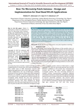
This paper presents the design and implementation of dual stacked identical Yagi antenna. An Antenna is an essential terminal device in all forms of communication and radar systems. Without an antenna there would be neither communication system nor radar system. An antenna acts as a source as well as a sensor of electromagnetic waves. The design was done using an online Yagi calculator software AN SOF Antenna Simulator which calculated the length, diameter, and the spacing of the materials elements and boom used in the construction. The Yagi antenna implementation was carried out using a cutting machine in cutting off various lengths of the elements specified by the Yagi calculator software. Thereafter, the elements were arranged on the aluminum boom and the coaxial cable impedances and dipole element were matched. The identical Yagi antennas were stacked 1020 mm center to center spacing vertically leading to an increase in gain of 15.4 dBwhen compared with 12.7 dBgain obtainable from a single Yagi antenna and larger capture area effective aperture .This design was able to solve the problems of underground noise, interference, low picture quality, low gain, and large beamwidth associated with a single Yagi antenna. This antenna can be used for UHF 3003000 MHz applications. J. Ilouno | M. Awoji | J. E. Onuh "Design and Implementation of Dual-Stacked Identical Yagi Antenna for UHF Applications" Published in International Journal of Trend in Scientific Research and Development (ijtsrd), ISSN: 2456-6470, Volume-2 | Issue-4 , June 2018, URL: https://www.ijtsrd.com/papers/ijtsrd14377.pdf Paper URL: http://www.ijtsrd.com/physics/other/14377/design-and-implementation-of-dual-stacked-identical-yagi-antenna-for-uhf-applications/j-ilouno<br>

E N D
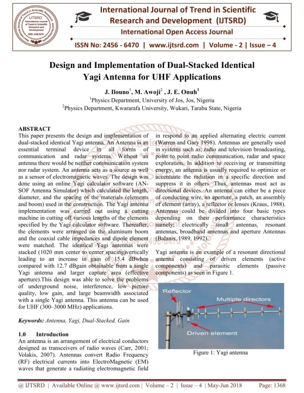
International Research Research and Development (IJTSRD) International Open Access Journal International Open Access Journal International Journal of Trend in Scientific Scientific (IJTSRD) ISSN No: 2456 - 6470 | www.ijtsrd.com | Volume nd Implementation of Dual-Stacked Identical ISSN No: 2456 6470 | www.ijtsrd.com | Volume - 2 | Issue – 4 Design and Implementation Yagi Antenna Yagi Antenna for UHF Applications Stacked Identical J. Ilouno J. Ilouno1, M. Awoji2 , J. E. Onuh1 Physics Department, University of Jos, Jos, Nigeria Physics Department, Kwararafa University, Wukari, Taraba State, Nigeria Kwararafa University, Wukari, Taraba State, Nigeria 1Physics Department, University of Jos, Jos, Nigeria 2Physics Department, in respond to an applied alternating electric current (Warren and Gary 1998). Antennas are generally used in systems such as; radio and television broadcasting, point to point radio communication, radar and space exploration. In addition to receiving or transmitting energy, an antenna is usually required to optimize or accentuate the radiation in a specific direction and suppress it in others. Thus, antennas must act as directional devices. An antenna can either be a piece of conducting wire, an aperture, a patch, an assembly of element (array), a reflector or lenses ( Antennas could be divided into four basic types depending on their performance characteristics namely; electrically small antennas, broadband antennas and aperture Antennas (Balanis, 1989, 1992). Yagi antenna is an example of a resonant directional antenna consisting of driven elements (active components) and parasitic components) as seen in Figure 1. ABSTRACT This paper presents the design and implementation of dual-stacked identical Yagi antenna. An Antenna is an essential terminal device communication and radar systems. Without an antenna there would be neither communication system nor radar system. An antenna acts as a source as well as a sensor of electromagnetic waves. The design was done using an online Yagi calculator software (AN SOF Antenna Simulator) which calculated the length, diameter, and the spacing of the materials (elements and boom) used in the construction. The Yagi antenna implementation was carried out using a cutting machine in cutting off various lengths of the elements specified by the Yagi calculator software. the elements were arranged on the aluminum boom and the coaxial cable impedances and dipole element were matched. The identical Yagi antennas were stacked (1020 mm center to center spacing)vertically leading to an increase in gain of 15.4 dBwhen compared with 12.7 dBgain obtainable from a single Yagi antenna and larger capture area (effective aperture).This design was able to solve the problems of underground noise, interference, low picture quality, low gain, and large beamwidth associated with a single Yagi antenna. This antenna can be used for UHF (300–3000 MHz) applications. Keywords:Antenna, Yagi, Dual-Stacked, Gain 1.0 Introduction An antenna is an arrangement of electrical conductors designed as transceivers of radio waves (Carr, 2001; Volakis, 2007). Antennas convert Radio Frequency (RF) electrical currents into ElectroMagnetic (EM) waves that generate a radiating electromagnetic field waves that generate a radiating electromagnetic field This paper presents the design and implementation of stacked identical Yagi antenna. An Antenna is an terminal device communication and radar systems. Without an antenna there would be neither communication system nor radar system. An antenna acts as a source as well as a sensor of electromagnetic waves. The design was Yagi calculator software (AN- SOF Antenna Simulator) which calculated the length, diameter, and the spacing of the materials (elements ternating electric current ). Antennas are generally used in in all all forms forms of of in systems such as; radio and television broadcasting, point to point radio communication, radar and space exploration. In addition to receiving or transmitting na is usually required to optimize or accentuate the radiation in a specific direction and suppress it in others. Thus, antennas must act as directional devices. An antenna can either be a piece of conducting wire, an aperture, a patch, an assembly ent (array), a reflector or lenses (Kraus, 1988). Antennas could be divided into four basic types depending on their performance characteristics electrically small antennas, broadband antennas and aperture Antennas The Yagi antenna implementation was carried out using a cutting various lengths of the elements specified by the Yagi calculator software. Thereafter, the elements were arranged on the aluminum boom and the coaxial cable impedances and dipole element were matched. The identical Yagi antennas were er to center spacing)vertically leading to an increase in gain of 15.4 dBwhen compared with 12.7 dBgain obtainable from a single Yagi antenna and larger capture area (effective aperture).This design was able to solve the problems antennas, antennas, resonant resonant Yagi antenna is an example of a resonant directional antenna consisting of driven elements (active components) and parasitic components) as seen in Figure 1. elements elements (passive (passive rference, low picture quality, low gain, and large beamwidth associated with a single Yagi antenna. This antenna can be used Stacked, Gain electrical conductors designed as transceivers of radio waves (Carr, 2001; ). Antennas convert Radio Frequency (RF) electrical currents into ElectroMagnetic (EM) Figure 1: Yagi antenna Figure 1: Yagi antenna @ IJTSRD | Available Online @ www.ijtsrd.com @ IJTSRD | Available Online @ www.ijtsrd.com | Volume – 2 | Issue – 4 | May-Jun 2018 Jun 2018 Page: 1368
International Journal of Trend in Scientific Research and Development (IJTSRD) ISSN: 2456-6470 The driven elements are connected directly to the transmission line (coaxial cable) and receive power from the source. Whereas, the parasitic elements are not connected to the transmission line and receive energy only through mutual induction. Theparasitic elements (directors and reflectors) modify the radiation pattern of the radio waves emitted by the driven element and direct them in a narrow beam in one direction and are arranged parallel to the driven elements. The reflector is usually longer than the driven element by 5% and acts as a concave mirror because it reflects the electromagnetic energy incident on it from the driven elements. The director is shorter than the driven element by 5% and acts as a convex mirror as it beams up the incident energy from driven element (Milligan, 2005). Antenna gain is the measure of the ability of antenna arrays to concentrate the radiated power in a given direction. High-gain antenna radiates energy in a particular direction whereaslow-gain antenna radiates energy in all directions equally. Gain is described using terms suc has antenna gain, power gain, directivity or directive gain. The antenna gain of the Yagi antenna isgreatly dependent on the dipole gain and the number of elements; and is given by (Ochalaand Okeme, 2011): G = 1.66 N where 1.66 is the dipole gain and N is the number of elements When Yagi antennas are stacked, there is an increase in gain and a decrease in the beam-width. The increased gain is due to the reduction in beam-width. There are two types of stacking namely; vertical stacking and horizontal stacking (Blake, 1996; Balanis, 2005, 2008). Stacking two identical antennas on a common vertical mast as seen in Figure 2 significantly narrows the vertical beam-width angle. That is, vertically stacked antennas effectively reject those interfering signals arriving from above or below their horizontal plane than that of a single antenna. In this process, gain increases with about 2.5 dB over that of a single antenna (Straw, 2000). Figure 2: Vertical dual-stacked antenna While stacking two identical Yagi antennas side by side in a horizontal plane significantly narrows the horizontal beam-width angle. That is, the antenna combination “sees” fewer interfering signals arriving from the sides while its vision up and down (in a vertical plane) is virtually unaffected. In this process, gain increases approximately 1.2 dB over that of a single antenna (Straw, 2000). The stacking distance can be calculated using Equation 2 (Milligan, 2005). S = ?? where S is the stacking distance and BW is the Beam-Width angle This research work is carried out to solve the problems of underground noise, interference, picture quality, low gain, and large beam-width associated with a single Yagi antenna by stacking two identical Yagi antennas. Vertical stacking was used in the implementation because of the higher gain and greater coverage area. 2.0 Materials and Methods Materials The materials used are: 1.Aluminum Boom 2.Screw nails 3.Elements 4.Coaxial cable (75 Ω) 5.Plastic insulators 6.Tape 7.Drilling machine 8.Hacksaw 9.Mast or pole for mounting of the antenna Methods Design of Yagi Antenna An online Yagi antenna calculator (AN-SOF Antenna Simutor) was used for the simulation with design ?? (2) (1) @ IJTSRD | Available Online @ www.ijtsrd.com | Volume – 2 | Issue – 4 | May-Jun 2018 Page: 1369
International Journal of Trend in Scientific Research and Development (IJTSRD) ISSN: 2456-6470 frequency of 889 MHz. The Yagi antenna designed has 8 elements: a reflector, a driven element, and 6 directors with dimensions shown in Table 2 Design Implementation The antenna was constructed using aluminum rods for antenna elements, 2cm-squared metal rodas boom, hacksaw for cutting the materials, gimlet for drilling holes, screw nails for fastening theelements to the boom, measuring tape, welding machine, 75-ohm coaxial cable as transmissionline and feeders to house the terminals of the folded dipoles.The elements were first measured as stated in Table 2. Holes were drilled at the midpoints of the aluminum rods and boom constructed. A reflectorunit and six directors were cut out. Holes were drilled on them and the directors were screwed into their appropriate positions. Plastic insulators were used to insulate the directors form the supporting boom.The folded dipole (driven element) was constructed by folding aluminium rod on a bending jig to obtain the folded dipole.A junction box was used to support the folded dipole on the boom. Openings were made on the side of the junction box using a drilling machine to allow fitting of the dipole and the coaxial cable. The feeder was fixed to the director boom with screw nails and the terminal of the folded dipole was then fixed to the inside of the feeder. With the feeder and folded dipole in place, the reflector and director units were fixed.The relative spacing between elements for optimal reception was determined as follows as shown in Table 3.The antenna was duplicated and were stacked vertically at 1020 mm. Approximately one wavelength spacing (at lowest channel frequency) between antennas was maintained. Finally, the folded dipoles were connected together by means ofa coaxial cable which serves as the transmission line. 3.0 Results Table 1: Length of rodrequired to produce resonant dipole Length to Diameter ratio(L/D) required 5000 2 0.49λ 50 5 0.475λ 10 9 0.455λ Table 2: Simulation Result Element Distance driving point of element(mm) Reflector 139 Director 1 Director 2 Director 3 Director 4 Director 5 Director 6 for Distance expressed as fractions wavelength of the driven 0.28 0.11 55 110 0.23 165 0.34 275 0.56 385 0.80 495 1.02 Table 3: Normalized Spacing between elements Relative Spacing 0.29λ ??,−? 0.110λ ??,? 0.227λ ??,? 0.227λ ??,? 0.227λ ??,? 0.227λ ??,? 0.227λ ??,? Table 4: Single and Stacked Yagi results compared Parameters Single Yagi Forward gain 12.720 dB Backward gain 3.415 dB Front-Back ratio 9.306 dB Beam-Width 47 degrees Signal strength 67% Stacking distance _ 4.0 Discussion Stacking two identical Yagi antennas produced an increase in 2.6 dB more forward gain as seen in Table 4. Vertical stacking reduces the vertical beamwidth and also introduced extra sidelobes in the vertical (elevation) radiation pattern. When antennas are stacked only vertically, the horizontal radiation Stacked Yagi 15.400 dB 4.394 dB 11.006 dB 23.5 degrees 76% 1020 Percent Shortening Resonant length Dipole thickness class Very thin Thin Thick @ IJTSRD | Available Online @ www.ijtsrd.com | Volume – 2 | Issue – 4 | May-Jun 2018 Page: 1370
International Journal of Trend in Scientific Research and Development (IJTSRD) ISSN: 2456-6470 11)Volakis, J.G. (2007). Antenna Engineering Handbook. 4th Ed.: McGraw-hill. pattern of the array will be the same as the individual Yagi.Stacking too far apart will increase the vertical sidelobe levels and make the vertical pattern narrower as the sidelobes eat into the main lobe. Wider stacking will also make the antenna bigger and less strong. Closer stacking will make the vertical pattern wider, and decrease the vertical sidelobelevels. Although this will result in serious loss of gain if taken too far, it may be a valid trade-off to obtain a cleaner vertical pattern. Vertical stacking improves both gain and vertical directivity. This helps reduce airplane flutter and attendant picture roll, and certain types of ground noise and ground reflections. 5.0 Conclusion The results of this finding have shown that dual- stacked Yagi antenna offers high gain compared with single Yagi antenna in operation coveringchannels in UHF bands. This design when properly matched to a feeder cable can solve the problems of underground noise, interference, low picture quality, low gain, and large beam-width posed by single Yagi antenna. Reference 1)Balanis, C.A. (1989). Advanced Engineering Electromagnetics, Wiley, New York. 12)Warren L.S. and Gary A.T. (1998).Antenna Theory and Design. 2nd Ed, New York: JohnWileyand Sons Inc.. 2)Balanis, C.A. (1992). Antenna Theory: A Review, “pro’’. IEEE, vol. (80). 3)Balanis, C.A. (2005). Antenna Theory: Analysis and Design, 3rd Ed. New Jersey: John Wiley and Sons. 4)Balanis, C.A. (2008). Modern Antenna Handbook. New York: John Wiley and Sons Inc.. 5)Blake, L.V. (1996). Antennas. New York: John Wiley and Sons. 6)Carr, J.J. (2001). Practical Antenna Handbook. 4th Ed. USA: McGraw-Hill. 7)Kraus, J.D. (1988). Antennas. New York: McGraw-Hill. 8)Milligan, T.A. (2005).Modern Antenna Design. New Jersey: John Wiley and Sons. 9)Ochala, I. and Okeme, I.C. (2011). Design and Implementation of a High-Gain Compound YagiAntenna. Advances in Applied Science Research, 2 (6), 41-50. 10)Straw, D. (2000). The ARRL Antenna Book. 19th Ed, USA: The American Radio Relay League. @ IJTSRD | Available Online @ www.ijtsrd.com | Volume – 2 | Issue – 4 | May-Jun 2018 Page: 1371