Download
1 / 16
160 likes | 171 Views
Construction is a vital part of every developing country in this era. Every country has specific building design codes which provide the standards to engineers for the design of various structural components like the beam, column, and slab. Analysis and design Reinforcement concrete building of every country is based on their geographical location. Seismic forces are one of the major natural forces causing huge damage to lives and economy. So that one can understand the difference and can appropriate for best guidelines for safety to lives and economy. In today's world of globalization, an engineer must be efficient enough to understand and handle different codes. In this paper, a comparative study is presented for analysis and design of reinforced concrete building under seismic forces for four codal Guidelines IS 1893 2002, Euro code 8, Japan 2007 and ASCE 7 10 using Staad Pro. The comparative study includes the comparison building base shear, bending moment, shear force, percentage of steel, required area, displacement, and story drift. For seismic Analysis and design, the building elements like beam and column is also compared using these countries RC building code. Tabish Izhar | Samreen Bano | Neha Mumtaz "Comparative Study on Analysis and Design of Reinforced Concrete Building under Seismic Forces for Different Codal Guidelines" Published in International Journal of Trend in Scientific Research and Development (ijtsrd), ISSN: 2456-6470, Volume-3 | Issue-4 , June 2019, URL: https://www.ijtsrd.com/papers/ijtsrd23819.pdf Paper URL: https://www.ijtsrd.com/engineering/structural-engineering/23819/comparative-study-on-analysis-and-design-of-reinforced-concrete-building-under-seismic-forces-for-different-codal-guidelines/tabish-izhar<br>

E N D
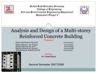
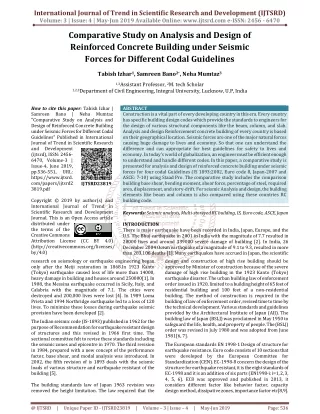
International Journal of Trend in Scientific Research and Development (IJTSRD) Volume: 3 | Issue: 4 | May-Jun 2019 Available Online: www.ijtsrd.com e-ISSN: 2456 - 6470 Comparative Study on Analysis and Design of Reinforced Concrete Building under Seismic Forces for Different Codal Guidelines Tabish Izhar1, Samreen Bano2*, Neha Mumtaz3 1,3Assistant Professor, 2M. tech Scholar 1,2,3Department of Civil Engineering, Integral University, Lucknow, U.P, India How to cite this paper: Tabish Izhar | Samreen Bano | "Comparative Study on Analysis and Design of Reinforced Concrete Building under Seismic Forces for Different Codal Guidelines" Published in International Journal of Trend in Scientific Research and Development (ijtsrd), ISSN: 2456- 6470, Volume-3 | Issue-4, June 2019, pp.536-551, URL: https://www.ijtsrd. com/papers/ijtsrd2 3819.pdf Copyright © 2019 by author(s) and International Journal of Trend in Scientific Research and Development Journal. This is an Open Access article distributed under the terms of the Creative Commons Attribution License (CC BY 4.0) (http://creativecommons.org/licenses/ by/4.0) research on seismology or earthquake engineering began only after the Meiji restoration in 1868.In 1923 Kanto (Tokyo) earthquake caused loss of life more than 14000, heavy damage in building and houses around 250000[1]. In 1908, the Messina earthquake occurred in Sicily, Italy, and Calabria with the magnitude of 7.1. The cities were destroyed and 200,000 lives were lost [4]. In 1989 Loma Prieta and 1994 Northridge earthquake led to a loss of 120 lives. To minimize these losses during earthquake seismic provision have been developed [2]. The Indian seismic code (IS-1893) published in 1962 for the purpose of Recommendation for earthquake resistant design of structures and this revised in 1966 first time. The sectional committee felt to revise these standards including the seismic zones and epicentre in 1970. The third revision in 1984, prepared with a new concept of the performance factor, base shear, and modal analysis was introduced. In 2002, the fifth revision of is 1893 deals with the seismic loads of various structure and earthquake resistant of the building [5]. The building standards law of Japan 1963 revision was removed the height limitation. The law required that the ABSTRACT Construction is a vital part of every developing country in this era. Every country has specific building design codes which provide the standards to engineers for the design of various structural components like the beam, column, and slab. Analysis and design Reinforcement concrete building of every country is based on their geographical location. Seismic forces are one of the major natural forces causing huge damage to lives and economy. So that one can understand the difference and can appropriate for best guidelines for safety to lives and economy. In today’s world of globalization, an engineer must be efficient enough to understand and handle different codes. In this paper, a comparative study is presented for analysis and design of reinforced concrete building under seismic forces for four codal Guidelines (IS 1893:2002, Euro code 8, Japan-2007 and ASCE: 7-10) using Staad Pro. The comparative study includes the comparison building base shear, bending moment, shear force, percentage of steel, required area, displacement, and story-drift. For seismic Analysis and design, the building elements like beam and column is also compared using these countries RC building code. Keywords: Seismic analysis, Multi-storeyed RC building, IS, Euro code, ASCE, Japan INTRODUCTION There is major earthquake have been recorded in India, Japan, Europe, and the U.S. The Bhuj earthquake in 2001 in India with the magnitude of 7.7 resulted in 20000 lives and around 339000 severe damage of building [2]. In India, 26 December 2004 Ocean earthquake of a magnitude of 9.1 to 9.3, resulted in more than 283,106 deaths [1]. Many earthquakes have accrued in Japan, the scientific design and construction of high rise building should be approved by Minister of construction because of the severe damage of high rise building in the 1923 Kanto (Tokyo) earthquake disaster. The urban building law of enforcement order issued in 1920, limited to a building height of 65 feet of residential building and 100 feet of a non-residential building. The method of construction is required in the building of law of enforcement order, revised time to time by the technical development. Various standards and guidelines provided by the Architectural Institute of Japan (AIJ). The building law of Japan (BSLJ) was proclaimed in May 1950 to safeguard the life, health, and property of people. The (BSLJ) order was revised in July 1980 and was adopted from June 1981[6, 7]. The European standards EN 1998-1 Design of structure for earthquake resistance. Euro code consists of 10 sections that were developed by the European Committee for Standardization (CEN). EC-1998-8 concern the design of the structure for earthquake resistant, it is the eight standards of EC-1998 and it is an addition of six parts (EN1998-i: i=1, 2, 3, 4, 5, 6). EC8 was approved and published in 2013, it considers different factor like behavior factor, capacity design method, dissipative zones, importance factor etc[8,9]. Neha Mumtaz IJTSRD23819 @ IJTSRD | Unique Paper ID - IJTSRD23819 | Volume – 3 | Issue – 4 | May-Jun 2019 Page: 536
International Journal of Trend in Scientific Research and Development (IJTSRD) @ www.ijtsrd.com eISSN: 2456-6470 The first modern code containing seismic provision is generally admitted to be the first edition of the uniform building code. National earthquake hazard reduction program recommended provisions developed by building science safety council in the USA (BSSC 1997). In 1937, the zonal map introduced with the concept of the different seismic resistant building. In 1988 UBC revised by structural engineering association of California (SEAOC). The (SEAOC) formed by Applied technology council, consider the introduction of site factor and occupancy importance factor. ASCE-7-10 utilize seismic design category (SDC) concept which differentiates the structure according to the seismic risk level [10, 11]. Ahmed M. EI Kholy at al. [3] compare the Egyptian code 2012 with EC 8-2013, IBC 2015 and UBC 1997; consider residential shear wall RC buildings in Egypt. Muhammad Mostafijur at al. [2] present seismic performance of reinforcement concrete buildings designed according to codes in Bangladesh, India, and the USA. The structures were modeled and design software ETABS NL (version 9.6). Masayoshi Nakashima [12] compares EC8 and the Japanese seismic design code (BCJ) for steel moment frames and braced frames. In this paper EC8 is 2.5 times larger force for his limit state. Marjan Faizan and Yuji Ishiyama [13] compare the seismic codes of Japan (BSLJ) 1981; USA (IBC) 2000 & Iran (ICS) 1999 are used for comparing the similarity and differences. C. Bhatt, R. Bento [14] compares the code of America and European, on the nonlinear static analysis of RC building. In this paper, five stories RC concrete building consider and result compare with nonlinear dynamic analysis. By Weizi Zhang and Bahram m. Shahrooz[15] present the comparison between ACI and AISC for concrete- filled tabular columns(CFTs), defined their potential capacity. Angelica Walsh at al. [16] compares three climatic zoning methodologies for structure and find out the difference in results for a small country climatic variation. Sameh A. EI-Betar [17] presents the seismic performance of existing RC framed building by nonlinear static pushover analysis. Ali Ergun at al. [18] presents the Premodern code (1998 Turkish earthquake code) to consider the seismic performance of RC building. Ali Ruzi Ozuygur [19] evaluates the structural design of a 50-story tall reinforcement concrete residential building, which was planned to be constructed in Istanbul. Its seismic performance has been checked by nonlinear time history analysis. Leonardo Avila at al. [20] presents the seismic performance of asymmetric masonry building. Mohsen Kohrangi [21] comparison consists of sequential steps for identifying understanding the similarities of the Key elements informed the seismic hazards models. Kristijan Kolozvari [22] evaluates the seismic performance and behavior of high rise RC coupled wall building with the help of dynamic analysis by modeling approach. M. Mosleh et al.[23] in this research two existing RC irregular building analyzed with EC 8 and purposed for co-linear analysis at different levels Global and Local. Jose Barros [24] this paper evaluates a different procedure for the structural design that gives the behaviour of frequent and rare earthquakes. A two-story school building is considered for study case. S. Malekpour at all.[25] this paper introduces the steel moment resisting frames by using three country code, Iranian, European and Japanese codes. The seismic performances of these codes are almost identical but differ for high rise building. Gang Shi at all.[26] - present the paper which compares and design of steel moment resisting frame by the different country code and find that Chinese code designed steel moment resisting frame exhibit 20% to 150% larger resistance and stiffness than U.S. & Euro code. This paper present comparison of four seismic codes (IS1893-2002, ASCE7-10, EC8-2013, BSLJ) and find out the difference and similarities of their codes. The analysis and design should be done by the software STAAD PRO V8i. The structure designed in India should be confirmed from the Indian standards code. The seismic design requirements of Indian standards and U.S. of the structure depends upon the seismic zoning system, site classification, fundamental period, response reduction factor, important factor, story drift and base shear are given in table 1. There are different parameter of Japan and Europe which are given table 2. Every code provides approximate formulas for estimating the time period and calculating base shear, lateral forces, and other required parameters. Objective of Study:- The main purpose of this study is to bring out a detailed seismic analysis and structural design on simulation tool STAAD PRO of a rectangular plan of multi-storey building. This study is focused to carry out the advantage of seismic design of multi-storey building using different country code with STTAD PRO at global level with ease of use. This numerical study comprises of- 1. To understand the accuracy of software’s for analysis and design of multi-storey building. 2. To compare the results and behaviour of structures using different country code. Simulation Tool STAAD PRO:- STAAD stands for Structural Analysis and Design. STAAD PRO is a general purpose structural analysis and design programme with applications primarily in the building industry-commercial buildings, bridges and highways structures etc. It was the first structural software which adopted for the analysis of matrix problems. The programme hence consists of the following facilities to enable this work. Graphical model generation utilities as well as text editor based commands for creating the mathematical model. Beam and column are represented using lines. Walls, slabs and panel type member are represents using triangular and quadrilateral finite elements. These utilities enable the users to create the geometry, assign properties, orient cross sections as desired, assign materials like steel, concrete, timber, aluminium, safety supports, and apply loads for desired loading case. Results viewing, result verification and report generation tools for examining displacement diagrams, bending moment and shear force diagram, beam etc. Comparison of seismic provision The different seismic provisions and standards of different countries are shown in table in table 1 & 2 respectively. The factor of safety for different loading case for country code is represented in table 3. and @ IJTSRD | Unique Paper ID - IJTSRD23819 | Volume – 3 | Issue – 4 | May-Jun 2019 Page: 537
International Journal of Trend in Scientific Research and Development (IJTSRD) @ www.ijtsrd.com eISSN: 2456-6470 Table 1: Comparison of seismic provisions of IS 1893-2002[5] and ASCE 7-10[2] IS 1893-2002[5] The country divided into four zones (II, III, IV, and V) zone II Z = 0.10 zone III Z = 0.16 zone IV Z = 0.24 zone V Z = 0.36 Parameters Zoning system ASCE 7-10[2] i. Each region is assigned a location-specific mapped Spectral acceleration parameter (SS, short period and S1, 1sec). ii. SS & S1 are modified for Site Class effects to get Maximum Considered Earthquake (MCE) spectral Response acceleration parameters (SMS and SM1). iii. The design spectral acceleration SDS and SD1 parameters can be obtained by dividing SMS and SM1 parameters by 1.5. Average shear wave velocity (ʋs), average field standard penetration resistance (n), and average undrained shear strength(Su) for the top 30.5m are used to classify different sites. The approximate fundamental period for “Reinforced Concrete Moment Resisting Frame” Ta= 0.0466hn0.9 , hn in meter. i. Ordinary moment resisting Frame (OMRF), R = 3 ii. Intermediate Moment Resisting Frames (IMRF) R = 5 Depends upon risk categories (I, ii, iii, iv)– ASCE 7 has four seismic important factor I = 1.0, 1.0, 1.25, 1.5 respectively. Allowable “inelastic” story drifts are limited to 0.020Hstory for a commercial building having risk category I or II. Design lateral force calculated from static analysis is V = Cs× W where Cs = the seismic response coefficient CS = Site Classification of site depends upon standard penetration test (N). classification Approximate fundamental period Response reduction factor The approximate fundamental period for “Reinforced Concrete Moment Resisting Frame” Ta= 0.075hn0.75 , hn in meter. i.Ordinary moment resisting Frame (OMRF), R =3 ii. Special moment resistant Frame (SMRF), R = 5 i.Important service and community building I =1.5 ii.All other Buildings I = 1.0 Allowable “elastic story drifts are 0.004Hstory for all the structures irrespective of any structure under risk category. Design lateral force calculated from the static analysis is V = x Important factor Drift criteria Minimum design lateral force xW Where (S/g) = spectral response acceleration parameter for MCE response spectrum corresponding to Ta, W = the seismic weight of the building And W = the seismic weight of the building. Story shear- Q = VB Where Qi = design lateral force at floor i, Wi = seismic weight of floor i, Hi = height of floor I measured from base N = number of story. i. For rocky or hard soil sites, Sa/g = i.Spectral Acceleration, For T < T0, Sa = SDS (0.4 + 0.6T/T0 ) T0=0.2.SD1/SDS ii. T0> T > TS, Sa=SDS, TS = SD1/SDS iii. TS > T > TL, Sa = SD1/T where TL=long period OR transition period iv. T > TL, Sa = SD1 TL/T2 Response spectrum ii. For medium soil sites, Sa/g = iii. For soft soil sites, Sa/g= @ IJTSRD | Unique Paper ID - IJTSRD23819 | Volume – 3 | Issue – 4 | May-Jun 2019 Page: 538
International Journal of Trend in Scientific Research and Development (IJTSRD) @ www.ijtsrd.com eISSN: 2456-6470 Table 2: Comparison of seismic provisions of EC 8 2004[26], BSLJ [6, 25] BSLJ [6,25] Parameters EC-8 [26] National territories shall be subdivided by the National Authorities into seismic zones, Depending on the local hazard. The hazard is described by R, The parameter modified by the Importance Factor the design Ground acceleration (on type A ground) R. R= Reduction factor Classification of the site depends upon standard penetration (N) test and shear wave velocity (ʋs). R,is to become Z= seismic zone factor 0.7 to 1.0. The BSLJ seismic zoning dividing Japan into three zones. The seismic zoning coefficient Z is 1.0, 0.9,0.8 and 0.7 Zoning system = The Japanese procedure evaluates a kind of simplified period (T G ) of the upper part of the ground - above the engineering Base. Ta = 0.1 N for moment resisting frame buildings not exceeding 12 stories and having a minimum story height of 3m is also permitted. (N is the number of stories) The natural period- T = (0.002+0.01 )H = ratio of stories by steel and timber construction Rt is the design spectral coefficient- Rt=1.0 T<Tc Rt=1.0-0.2 Tc ≤ T<2Tc Site classification Approximate fundamental period The mean return period TR is given by TR = 1/V TR = TL/ln(1-P) Response reduction factor ----- Rt=1.6Tc/T 2Tc≤T Important factor divided into four class (I, ii, iii, iv) Class factor i 0.8 Agriculture building Ii 1.0 Ordinary building iii culture hall. Hospital, power plant, fire station i.for buildings having non-structural elements of brittle materials attached to the structure: d rv≤0.005h ii. for buildings having ductile non-structural elements: d rv≤0.0075h iii.for buildings having non-structural elements fixed in a way so as not to interfere with structural deformations, or without non-structural elements: drv≤0.010h Important Buildings Important factor Not available 1.2 Schools, assembly halls, iv 1.4 Story drift limitations- In BSLJ, the drift of each story of the building caused by the moderate earthquake motions shall not exceed 1/200 of the story height. This value can be increased to 1/120 if the nonstructural members shall have no severe damage at increased story drift limitation. Drift criteria Story shear coefficient- Ci = Z Rt Ai C0 story shear- Qun = DSFesCi Where, Z is the seismic zoning coefficient, Rt is the design spectral coefficient, Ai is the lateral shear distribution factor and C0 is the standard shear coefficient = 0.2 and for severe earthquake motions, Ds is the structural coefficient, Fes is the shape factor and C0 = 1.0. = total dead load and live load above story i. Design response spectra at engineering bedrock S0(T) = Design response spectra at ground motion Sa(T) = Gs(T) Z S0(T) Where, S0 = basic design acceleration response spectra in m/s2 and T = natural period. Sa = design acceleration response spectra at ground surface m/s2, GS = surface soil layer amplification factor. Base Shear - VB = Sd(T1)W Minimum design lateral force Sd(T1) is the ordinate of the design spectrum corresponding to fundamental Period T1 of the structure and Wis the gravity load contributing W. The elastic response spectrumis divided in 4 different branches defined by the following expressions: 0≤T≤TB Se(T) = agS(1+T/TBƞ2.5-1) TB≤T≤TC Se(T) = agSƞ2.5 TC≤T≤TD Se(T) = agS(1+T/TBƞ2.5(TC/T) TD≤T≤4S Se(T) = agS ƞ2.5(T CT D/T) Response spectrum @ IJTSRD | Unique Paper ID - IJTSRD23819 | Volume – 3 | Issue – 4 | May-Jun 2019 Page: 539
International Journal of Trend in Scientific Research and Development (IJTSRD) @ www.ijtsrd.com eISSN: 2456-6470 Table 3: Load combination of IS1893-2002, ASCE7-10, BSLJ and EC-2 IS875-2002 [5] ASCE7-10 [2] 1.5(D+L) 1.4D 1.2(D+L±W) 1.2D+1.6L+0.5Lr 1.5(D±W) 1.2D+1.6Lr+(L OR 0.8W) 0.9D±1.5W 1.2D+1.6W+1.0L+0.5Lr 0.9D + 1.6W 0.9D + 1.0W 0.9D + 1.0E BSLJ [6,25] D+L+E D+L+S+E EC-2 [29] 1.35D+1.5L 1.0D+1.5W 1.35D+1.5L+0.9W Study Model:- A geometrically similar 10 story included 4 -bay by 4- bay reinforcement concrete ordinary moment resting frame was considered for all the codes. The height of each story was 3 m and a total height of 30 m. The width and length of the structure were 24 and 24 m respectively. The selected building was to represent an office building. The D.L. per unit area of the floor, consisting of the floor slab finishes etc. is 4 KN /m2. The weight of the partition on the floor can be assumed to be 2 KN/m2. The intensity of live load on each floor is 3KN/m2 and on the roof are 1.5 KN /m2. The soil below the foundation is hard and the building is located in Delhi. The plan area is given in figure 1 & 2. The 3-D structural model is shown in figure 3. The site soil classification and the response acceleration parameters and zone factor for this building are shown in Table 4. The load combination of dead load , live load, roof load and earthquake load, wind load for their four building code are given in Table 3. 1.Building parameter- Size of beam= 300x600 mm Size of column= 650x450 mm Size of building= 24x24 mm D.L. of slab including finishes 4 KN/m2 The weight of partition on floor 2 KN/m2 L.L. of each floor =3 KN/m2 L.L. on the roof =1.5 KN/m2 Soil below foundation is hard soil Table 4 Site location and classification of seismic Design parameters Code Zone coefficient /response acceleration parameters IS1893 Seismic zone: iv, (z) = 0.24 Importance factor (I) = 1 T = 0.96s ASCE7-10 Spectrum response acceleration Ss= 1.893, S1= 0.85, BSLJ Seismic zone: iv, (z) = 0.75 Ta = 0.1N sec , ɑ = 1 EC-8 Seismic zone: iii ag = 0.15g Importance factor (γ) = 1 2.Seismic weight- Floor area= 24x24 =576 Dead load =4 KN /m2 Weight of partitions = 2kN/m2 For live load up to and including =3KN/m2 Percentage of live load to be considered =2.5% Effective weight at each floor except the roof = 4.0+2.0+0.25+3 = 6.75 KN/m2 And at the roof = 4.0 KN/m2 Site class Type 2 (hard soil) Site class D (stiff soil) Soil type C Fig.1. 4 @ 6.00 m = 24 m plan view of the structure @ IJTSRD | Unique Paper ID - IJTSRD23819 | Volume – 3 | Issue – 4 | May-Jun 2019 Page: 540
International Journal of Trend in Scientific Research and Development (IJTSRD) @ www.ijtsrd.com eISSN: 2456-6470 Fig.2. Front view of the structure Fig.3. 3-D Structural Model of the structure Modelling and design of the structure for analysis:- The building should be consisting of three-dimensionally in the office purpose. Analysis, and design on software STAAD.pro V8 i. The column was considered as fixed support. Dead load, live load, and seismic load considered as per their code. Code used for concrete design- IS45 -2002, ACI 318-2008, AIJ & EC-2 Code used for Seismic design- IS1893-2002, BS-8110, IBC-2006 & Japanese code. *The code BS-8110 is used for seismic design of European code on Staad- pro V8i. *The code IBC-2006 is used for seismic design of American code on Staad- pro V8i. The specification used for concrete design- A grade of concrete -30 MPa Grade reinforcement - 415 MPa Concrete cover of the beam - 25mm Concrete cover of the column- 40mm Results and discussion- 1. The analysis and design of beam, column and storey drift at different level according to IS loading condition is evaluated in the terms of maximum axial force, maximum bending moment, maximum shear force, story drift and displacement as shown in Table 5,6 & 7. The graphical representation of the results is shown in figure from 4 to 11. Table 5: Analysis of beam as per IS loading with different code Code Maximum axial force (kN) Maximum Bending moment (kNm) IS1893 111.384 (1.5DL+LL) 252.542 (1.5DL+LL) EC-8 111.384 (1.5DL+LL) 252.542 (1.5DL+LL) ASCE 110.9 (1.5DL+EQX) 233.25 (1.5DL+EQX) BSLJ 92.398 (1.5DL+LL) 233.25 (1.5DL+LL) Maximum shear force (kN) 252.083 (1.5DL+EQX) 511.187 (1.5DL+EQX) 505.186 (1.5DL+LL) 162.564 (1.5DL+LL) @ IJTSRD | Unique Paper ID - IJTSRD23819 | Volume – 3 | Issue – 4 | May-Jun 2019 Page: 541
International Journal of Trend in Scientific Research and Development (IJTSRD) @ www.ijtsrd.com eISSN: 2456-6470 Fig.4. Axial force as per different code Fig.5. Bending moment as per different code Fig.6. Shear force with different code Analysis of beam in table 5 as per IS loading and its graphical results shows that the value of maximum axial force in beam is max for IS and EC but the min for BSLJ. The value of bending moment in beam is max for also IS and EC as compared to ASCE & BSLJ. The value of shear force in beam is max for EC but min for BSLJ. Table 6: Analysis of column as per IS loading with different code Maximum axial force (kN) (KNm) IS1893 5358.35 (1.5DL+LL) 487.852 (1.5DL+EQZ) EC-8 4781.278 (1.5DL+LL) 1065.58 (1.5DL+EQX) ASCE 5446.855 (1.5DL+LL) 1387.759 (1.5DL+EQX) BSLJ 5446.856 (1.5DL+LL) 202.681 (1.5DL+EQZ) Maximum Bending moment Maximum shear force (kN) 285.706 (1.5DL+EQZ) 684.447 (1.5DL+EQX) 784.251 (1.5DL-EQX) 94.047 (1.5DL+EQZ) Base shear (kN) 4294.75 4294.75 4124.012 4294.75 Code @ IJTSRD | Unique Paper ID - IJTSRD23819 | Volume – 3 | Issue – 4 | May-Jun 2019 Page: 542
International Journal of Trend in Scientific Research and Development (IJTSRD) @ www.ijtsrd.com eISSN: 2456-6470 Fig.7. Axial force as per different code Fig.8. Bending moment as per different code Fig.9. Shear force as per different code Fig.10. Base shear as per different code @ IJTSRD | Unique Paper ID - IJTSRD23819 | Volume – 3 | Issue – 4 | May-Jun 2019 Page: 543
International Journal of Trend in Scientific Research and Development (IJTSRD) @ www.ijtsrd.com eISSN: 2456-6470 Analysis of column in table 6 as per IS loading and its graphical results shows that the value of maximum axial force in column is max for ASCE & BSLJ but the min for EC. The value of bending moment in column is max for ASCE but min for BSLJ. The value of shear force in column is max for ASCE but min for BSLJ. The value of base shear is max for IS, BSLJ and EC but min for ASCE. Table 7: Story drift and Displacement of building as per IS loading with different code IS1893 EC-8 Drift Displacement Drift Displacement 3 0.9688 9.688 0.7586 0.7586 6 1.5244 2.4932 1.1780 1.9366 9 1.6076 4.1008 1.2096 3.1462 12 1.6140 5.7147 1.1643 4.3106 15 1.5976 7.3123 1.0850 5.3955 18 1.5634 8.8757 0.9767 6.3722 21 1.5094 10.3851 0.8394 7.2117 24 1.4305 11.8157 0.6727 7.8843 27 1.3096 13.1253 0.4780 8.3623 30 1.0541 14.1794 0.2730 8.6354 ASCI Displacement 2.6013 6.6385 10.7791 14.7561 18.4497 21.7575 24.5764 26.8023 28.3388 29.168 BSLJ Displacement 0.6915 1.7479 2.8141 3.8261 4.7608 5.6007 6.3281 6.9232 7.3625 7.6269 Height in m Drift 2.6013 4.0372 4.1405 3.9770 3.6936 3.3078 2.8190 2.2258 1.5365 0.8296 Drift 0.6915 1.0564 1.0662 1.0119 0.9347 0.8400 0.7274 0.5950 0.4393 0.2644 Fig.11. Value of drift at different level as per IS loading for different code The above table and figure shows that the variation of storey drifts and displacement varies according to height of building. It is clearly shown in table that the value of drift is increasing slightly and then decreases. 2. The analysis and design of beam, column and storey drift at different level according to their loading condition is evaluated in the terms of maximum axial force, maximum bending moment, maximum shear force, story drift and displacement as shown in Table 8, 9 & 10. The graphical representation of the results is shown in figure from 12 to 19. Table 8: Analysis of Beam as per their code loading Code Maximum Axial Force (kN) Maximum Bending moment (KNm) IS1893 111.384 (1.5DL+LL) 252.542 (1.5DL+LL) EC-8 141.976 (1.4DL+1.6LL+1.6RFL) 331.976(1.4DL+1.6LL+1.6RFL) ASCE 122.556 (1.2DL+LL+1.6RFL) 282.111 (1.2DL+LL+1.6RFL) BSLJ 76.007 (DL+LL+EQX) 168.362 (DL+LL+EQX) Maximum shear force (kN) 252.083 (1.5DL+EQX) 240.174 (1.4DL+1.6LL+1.6RFL) 493.048 (1.2DL+LL+RFL) 132.855 (DL+LL+RFL+EQX) Fig.12. Axial force as per different code @ IJTSRD | Unique Paper ID - IJTSRD23819 | Volume – 3 | Issue – 4 | May-Jun 2019 Page: 544
International Journal of Trend in Scientific Research and Development (IJTSRD) @ www.ijtsrd.com eISSN: 2456-6470 Fig.13. Bending moment as per different code Fig.14. Shear force as per different code Analysis of beam in table 8 as per their loading and its graphical results shows that the value of maximum axial force in beam is max for EC but the min for BSLJ. The value of bending moment in beam is max for EC but min for BSLJ. The value of shear force in beam is max for ASCE but min for BSLJ. Table 9: Analysis of Column as per their loading condition Maximum axial force (KN) m) IS1893 5358.35 (1.5DL+LL) 487.852 (1.5DL+EQZ) EC-8 4781.278 (1.5DL+LL) 1065.58 (1.5DL+EQX) ASCE 5446.855 (1.5DL+LL) 1387.759(1.5DL+EQX) BSLJ 5446.856 (1.5DL+LL) 202.681 (1.5DL+EQZ) Maximum Bending moment (KN- Maximum shear force (KN) 285.706 (1.5DL+EQZ) 684.447 (1.5DL+EQX) 784.251 (1.5DL-EQX) 94.047 (1.5DL+EQZ) Base shear (KN) 4294.75 4294.75 4124.012 4294.75 Code Fig.15. Axial force with different code Fig.16. Bending moment as per different code @ IJTSRD | Unique Paper ID - IJTSRD23819 | Volume – 3 | Issue – 4 | May-Jun 2019 Page: 545
International Journal of Trend in Scientific Research and Development (IJTSRD) @ www.ijtsrd.com eISSN: 2456-6470 Fig.17. Shear force as per different code Fig.18. Base shear as per different code Analysis of column in table 9 as per their loading and its graphical results shows that the value of maximum axial force in column is max for ASCE and BSLJ but the min for EC-8. The value of bending moment in column is max for ASCE but min for BSLJ. The value of shear force in column is max for ASCE but min for BSLJ. The value of base shear is max for IS, BSLJ and EC but min for ASCE. Table 10: Story drift and Displacement of building as per their code loading Height in m Drift Displacement Drift Displacement 3 0.9688 9.688 0.9688 9.688 6 1.5244 2.4932 1.5244 2.4932 9 1.6076 4.1008 1.6076 4.1008 12 1.6140 5.7147 1.6140 5.7147 15 1.5976 7.3123 1.5976 7.3123 18 1.5634 8.8757 1.5634 8.8757 21 1.5094 10.3851 1.5094 10.3851 24 1.4305 11.8157 1.4305 11.8157 27 1.3096 13.1253 1.3096 13.1253 30 1.0541 14.1794 1.0541 14.1794 IS1893 EC-8 ASCE Displacement 2.6931 6.8894 11.2218 15.4186 19.3539 22.9140 25.9791 28.4235 30.1260 31.055 BSLJ Displacement ......... ......... .......... ........... .......... ........... ............ ............. ........... ............ Drift 2.6931 4.1963 4.3324 4.1968 3.9353 3.5601 3.0651 2.4444 1.7025 0.964 Drift 0.3112 0.7865 1.2664 1.7217 2.1423 2.5203 2.2781 3.1154 3.3131 3.4321 Fig.19. Value of drift as different code The above table and figure shows that the variation of storey drifts and displacement varies according to height of building. It is clearly shown in table that the value of drift is increasing slightly and then decreases. @ IJTSRD | Unique Paper ID - IJTSRD23819 | Volume – 3 | Issue – 4 | May-Jun 2019 Page: 546
International Journal of Trend in Scientific Research and Development (IJTSRD) @ www.ijtsrd.com eISSN: 2456-6470 3. Now the concrete design of beam and column according to IS loading condition is evaluated in the terms of required area and percentage of steel as shown in Table 11 & 12. The graphical representation of the results is shown in figure from 20 to 23. Table 11: Concrete design of beam as per IS code loading Code Required area Percentage of steel IS456 4061.970 EC-2 4321.083 ACI 4452.23 AIJ 4224.11 1.76 1.10 1.29 1.02 Fig.20. Required area as per different code Fig.21. Percentage of steel as per different code The concrete design of beam in table 11 as per IS loading condition and its graphical results shows that the value of required area in beam is max for ACI but the min for IS. The value of % steel in beam is max for IS but min for AIJ. Table 12: Concrete design of column as per IS code loading 0.1 Main reinforcement Tie reinforcement IS456 24#20Ø 8mm@300mm c/c EC-2 36#25Ø 8mm@180mm c/c ACI 12#32Ø 12mm@110mm c/c AIJ 12#13Ø 10mm@320mm c/c Required area (mm2) Percentage of steel (%) 7539.82 9754 8862.8 1470.265 2.58 3.219 0.528 3.299 Fig.22. Required area as per different code @ IJTSRD | Unique Paper ID - IJTSRD23819 | Volume – 3 | Issue – 4 | May-Jun 2019 Page: 547
International Journal of Trend in Scientific Research and Development (IJTSRD) @ www.ijtsrd.com eISSN: 2456-6470 Fig.23. % of steel as per different code The concrete design of column in table 12 as per IS loading condition and its graphical results shows that the value of required area in column is max for EC but the min for AIJ. The value of % steel in column is max for AIJ but min for ACI. 4. Now the concrete design of beam and column according to their loading condition is evaluated in the terms of required area and percentage of steel as shown in Table 13 & 14. The graphical representation of the results is shown in figure from 24 to 27. Table 13: Concrete design of beam according as per their code loading Code Required area Percentage of steel IS456 4061.970 EC-2 2033 ACI 493.048 AIJ 223.19 1.76 1.10 1.19 1.02 Fig.24. Required area as per different code Fig.25. % of steel with different code The concrete design of beam in table 13 as per their loading condition and its graphical results shows that the value of required area in beam is max for IS but the min for AIJ. The value of % steel in beam is max for IS but min for AIJ. @ IJTSRD | Unique Paper ID - IJTSRD23819 | Volume – 3 | Issue – 4 | May-Jun 2019 Page: 548
International Journal of Trend in Scientific Research and Development (IJTSRD) @ www.ijtsrd.com eISSN: 2456-6470 Table 14: Concrete design of column according as per their code loading Main reinforcement Shear reinforcement 24#20Ø 2 legged 8 Ø@280mmc/c 4#20Ø(TOP) 4#12Ø(BOTTOM) 1 legged 8 Ø@157mmc/c 5#20Ø(TOP) 6#16Ø(BOTTOM) 2 legged 8 Ø@245mmc/c 3#20Ø(TOP) 5#16Ø(BOTTOM) 2 legged 12 Ø@245mmc/c Code IS456 EC-2 ACI AIJ Required area (mm2) Percentage of steel 7539.82 223.19 1474 1470.265 1.23 1.25 1.00 1.31 Fig.26. Required area as per different code Fig.27. % of steel as per different code The concrete design of column in table 12 as per their loading condition and its graphical results shows that the value of required area in column is max for IS but the min for EC. The value of % steel in column is max for AIJ but min for ACI. Conclusion:- The following conclusions are drawn from the computer simulation program carried out in this investigation: A. For Beam:- (i) Analysis as per IS loading- 1.Axial force is maximum as per IS & EC and minimum as per BSLJ. 2.Bending moment is maximum as per IS & EC and minimum as per ASCE & BSLJ. 3.Shear force is maximum as per EC and minimum as per BSLJ. (ii) Analysis as per their loading- 1.Axial force is maximum as per EC and minimum as per BSLJ. 2.Bending moment is maximum as per EC and minimum as per BSLJ. 3.Shear force is maximum as per ASCE and minimum as per BSLJ. (iii) Concrete design as per IS loading 1.Required area is maximum as per ACI and minimum as per IS. 2.Percentage of steel is maximum as per IS and minimum as per AIJ. (iv) Concrete design as per their loading 1.Required area is maximum as per IS and minimum as per BSLJ. 2.Percentage of steel is maximum as per IS and minimum as per AIJ. B. For Column:- (i) Analysis as per IS loading- 1.Axial force is maximum as per ASCE & BSLJ and minimum as per EC. 2.Bending moment is maximum as per ASCE and minimum as per BSLJ. 3.Shear force is maximum as per ASCE and minimum as per BSLJ. 4.Base shear is maximum as per IS, EC & BSLJ and minimum as per ASCE. @ IJTSRD | Unique Paper ID - IJTSRD23819 | Volume – 3 | Issue – 4 | May-Jun 2019 Page: 549
International Journal of Trend in Scientific Research and Development (IJTSRD) @ www.ijtsrd.com eISSN: 2456-6470 [10]ASCE/SEI 7-10. Minimum design loads for buildings and other structures. Reston, VA: American Society of Civil Engineers; 2010 [11]Edoardo M. Marino, Masayoshi Nakashima, and Khalid M. Mosalam Comparison of European and Japanese seismic design of steel building structures Kyoto University, Gokasho, Uji, Kyoto 611-0011, Japan Engineering Structures 27 (2005) 827–840 [12]Marjan Faizian and Yuji Ishiyama comparison of seismic codes of 1981 Japan (BSLJ), 2000 USA (IBC) and 1999 Iran (ICS) 13th World Conference on Earthquake Engineering Vancouver, B.C., Canada August 1-6, 2004 Paper No. 3168. [13]C. Bhatt, R. Bento A Comparison Between American and European Codes on the Nonlinear Static Analysis of RC Buildings 15th World Conference on Earthquake Engineering. [14]By Weizi Zhang and Bahram M. Shahrooz Comparison between ACI and AISC for concrete-filled tubular columns, Heriot-Watt University on 03/07/15. Copyright ASCE. [15]Ang´ Elica Walsh, Daniel C´ Ostola, Lucila C. Labaki Comparison of three climatic zoning methodologies for building energy http://dx.doi.org/doi:10.1016/j.enbuild.2017.04.044 [16]Sameh A. EI-Betar Seismic performance of the existing framed building, http://ees.elsevier.com/hbrcj [17]Ali Ergun, Nevzat kirac, Veli Bas, Aran The evaluation of structural properties of a reinforced concrete building designed according to pre-modern code considering seismic performance Doi:10.1016/j.engfailanal.2015.09.003, Reference: EFA 2693. [18]Ali Ruzi Ozuygur Performance-based seismic design of an irregular tall building – a case study, Doi:10.1016/j.istruc.2015.10.00 Reference: INSTRUCT 62. [19]Leonardo Avila, Graça Vasconcelos, Paulo B. Lourenço. Experimental seismic performance assessment of asymmetric masonry www.elsevier.com/locate/engstruct [20]Mohsen Kahurangi, Laurentiu Danciu, Paolo Bazzurro. Comparison between outcomes of the 2014 Earthquake Hazard Model of the Middle East (EMME14) and national seismic design codes: The case of Iran, www.elsevier.com/locate/soildyn [21]Kristijan Kolozvari, Vesna Terzic, Ross Miller, Daniel Saldana. Assessment of dynamic behavior and seismic performance of a high-rise RC coupled wall building, www.elsevier.com/locate/engstruc [22]A. Mosleh, H. Rodrigues, H. Varum, A. Costa, A. Arêde. Seismic behavior of RC building structures designed according to www.elsevier.com/locate/structures [23]José Barros, Hern án San ta-María. Seismic design of low -rise buildings based on frequent earthquake response spectrum https: / /Doi .org/10.1016/ j .job e.2018.11.005. [24]S. Malekpour, P. Seyyedi, F. Dashti, and J. Fallah Asghari. Seismic Performance Evolution of Steel Moment Frames Using Iranian, Euro code and Japanese code, The Twelfth East Asia-Pacific Conference on Structural (ii) Analysis as per their loading- 1.Axial force is maximum as per ASCE & BSLJ and minimum as per EC. 2.Bending moment is maximum as per ASCE and minimum as per BSLJ. 3.Shear force is maximum as per ASCE and minimum as per BSLJ. 4.Base shear is maximum as per IS, BSLJ & EC and minimum as per ASCE. (iii) Concrete design as per IS loading 1.Required area is maximum as per EC and minimum as per AIJ. 2.Percentage of steel is maximum as per AIJ and minimum as per ACI. (iv) Concrete design as per their loading 1.Required area is maximum as per IS and minimum as per EC. 2.Percentage of steel is maximum as per AIJ and minimum as per ACI. Reference:- [1]Yuji Ishiyama: Introduction to Earthquake Engineering and Seismic Codes 2012,http://iisee.kenken.go.jp/ [2]Muhammad Mostafijur Rahman, Sagar m. Jadhav, Bahram M. Shahrooz, seismic performance of reinforces concrete building designed according to codes in Bangladesh, India and U. S. University of Cincinnati, USA. [3]Ahmad M. EI-Kholy, Hoda Syed, Ayman A. Shaheen, Comparison of Egyptian code 2012 with Euro code 8- 2013, IBC 2015 and UBC 1997 for seismic analysis of residential shear-wall RC buildings in Egypt Volume 9, Issue 4, Pages 3425-3436, Nahda University NUB, Beni Suef. Egypt, 2018. https://en.wikipedia.org/wiki/1908_Messina_earthqua ke [4]IS-1893 Part 1. Criteria of earthquake resistant design of the structure, rev. 5, Bureau of Indian standards, Manak Bhawan, New Delhi, India 2002. [5]S. Otani, Recent developments in seismic Design criteria in Japan. In proceedings of an 11th world conference of earthquake engineering (11th WCEE), paper no. 2124. [6]S. Otani, Japanese seismic design of High rise reinforces concrete building-an example of performance-based design code and state of practice. In proceedings of a 13th world conference of earthquake engineering (13th WCEE), paper no. 5010. [7]CEN/TC 250 Committee. Euro code 8. Design of structure for earthquake resistant, part 1: General rules for buildings (European standard EN 1998-1) European Committee for Standardization (CEN); Belgium-2004 [8]CEN/TC 250 Committee. Euro code 8. Design of structure for earthquake resistant, part 1: General rules for buildings (European standard EN 1998-1) European Committee for Standardization (CEN); Belgium-2013ACI Committee 318. [9]ACI 318-14/ACI 318R-14, building code requirements for structural concrete and commentary. Farmington Hills, MI: American Concrete Institute; 2014. in the World, July efficiency applications, buildings, current codes, @ IJTSRD | Unique Paper ID - IJTSRD23819 | Volume – 3 | Issue – 4 | May-Jun 2019 Page: 550
International Journal of Trend in Scientific Research and Development (IJTSRD) @ www.ijtsrd.com eISSN: 2456-6470 Engineering and Construction, Procedia Engineering 14 (2011) 3331–3337. [25]Gang Shi, Fangxin Hu, Yongjiu Shi. Comparison of seismic design for steel moment frames in Europe, the United States, Japan and China, Journal of Constructional Steel Research 127 (2016) 41–53. [26]Masaomi Teshigawara Outline of Earthquake Provisions in the Japanese Building Codes Architectural Institute of Japan (ed.), Preliminary Reconnaissance Report of the 2011 Tohoku-Chiho Taiheiyo-Oki Earthquake, Geotechnical, Geological and Earthquake Engineering 23, DOI 10.1007/978-4-431-54097-7, © Springer Japan 2012. [27]CEN. Euro Code 8: Final draft of Euro Code 8: Design of structures for earthquake resistance — 1998-1:2004: General rules, seismic actions, and rules for buildings. Bruxelles: European Committee for Standardization; 2003 [28]F. Biasioli, G. Mancini, M. Just, M. Curbach, J. Walraven, S. Gmainer, J. Arrieta, R. Frank, C.Morin, F. Robert EUROCODE 2: Background & Applications design of concrete buildings by European commission 2014. @ IJTSRD | Unique Paper ID - IJTSRD23819 | Volume – 3 | Issue – 4 | May-Jun 2019 Page: 551