Download
1 / 116
1.19k likes | 1.29k Views
Seismic Design Methodology for Precast Concrete Floor Diaphragms. Research to Practice Webinar April 23, 2012. Dr. Ned M. Cleland, P.E Dr. Robert B. Fleischman Dr. S.K. Ghosh, P.E. Blue Ridge Design, Inc University of Arizona SKG Associates.

E N D
Seismic Design Methodology for Precast Concrete Floor Diaphragms Research to Practice Webinar April 23, 2012 Dr. Ned M. Cleland, P.E Dr. Robert B. Fleischman Dr. S.K. Ghosh, P.E. Blue Ridge Design, Inc University of Arizona SKG Associates Sponsored by the Earthquake Engineering Research Institute (EERI) and the Network for Earthquake Engineering Simulation (NEES)
Outline NEES/EERI Webinar April 23 2012 Introduce PCI/NSF/CPF DSDM Research Effort Review Key Behaviors of Precast Diaphragms and Design Philosophy Adopted Summarize DSDM Research Project Findings Present Precast Diaphragm Design Procedure Cover Precast Diaphragm Design Example Discuss Codification Efforts
Outline NEES/EERI Webinar April 23 2012 Introduce PCI/NSF/CPF DSDM Research Effort Review Key Behaviors of Precast Diaphragms and Design Philosophy Adopted Summarize DSDM Research Project Findings Present Precast Diaphragm Design Procedure Cover Precast Diaphragm Design Example Discuss Codification Efforts
Diaphragm Action Diaphragm action is intended to carry seismic forces horizontally in the floor slab to walls and frames… NEES/EERI Webinar April 23 2012
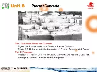
Precast Diaphragm Details Precast floors can be vulnerable due to the need to transfer forces at discrete locations across floor joints between precast panels NEES/EERI Webinar April 23 2012
Precast Diaphragm Past Performance NEES/EERI Webinar April 23 2012
DSDM Project Project Co-funders: CPF, PCI and NSF Objective: Develop an industry endorsed seismic design methodology for precast concrete diaphragms. Scope: Untopped and topped composite precast floor diaphragms. NEES/EERI Webinar April 23 2012
University of Arizona Robert Fleischman Consortium Leader University of California Lehigh University Industry Liaison San Diego Clay Naito, PI S. K. Ghosh, Co-PI DSDM Task Group Jose’ Restrepo, PI Richard Sause, Co-PI Producer Members Producer Members Industry Advisory Panel DSDM Consortium NEES/EERI Webinar April 23 2012
DSDM Task Group Graduate Researchers Dichuan Zhang, Ge Wan, Michael Mielke, Alicia Mullenbach, Univ. of Arizona Liling Cao, Rui Ren, Wesley Peter, Lehigh Univ. Matt Schoettler and Andrea Belleri, UCSD Industry Task Group S.K.Ghosh DSDM Task Group Chair President, S. K. Ghosh Associates R. Becker Vice President Spancrete Industries, Inc. N. Cleland President Blue Ridge Design, Inc. Tom D’Arcy President Consulting Engineers Group N. Hawkins Professor Emeritus Univ. of Illinois Doug Sutton Professor Purdue University Harry Gleich Vice President Metromont Prestress Paul Johal Research Director PCI Joe Maffei Engineering Consultant Rutherford & Chekene Engineers Susie Nakaki President The Nakaki Bashaw Group, Inc. Dave Dieter Vice-President MidState Precasters Chuck Magnesio Vice-President JVI, Inc NEES/EERI Webinar April 23 2012
Outline NEES/EERI Webinar April 23 2012 Introduce PCI/NSF/CPF DSDM Research Effort Review Key Behaviors of Precast Diaphragms and Design Philosophy Adopted Summarize DSDM Research Project Findings Present Precast Diaphragm Design Procedure Cover Precast Diaphragm Design Example Discuss Codification Efforts
Diaphragm Forces An aspect of diaphragm behavior not elucidated in the codes is the relationship of the design forces used in equivalent lateral force (ELF) procedures to the inertial forces that may actually develop in floors during a seismic event. Fleischman and Farrow, Eq. Eng & Struc. Dyn, 2001 Diaphragm peak inertial forces may significantly exceed current design values NEES/EERI Webinar April 23 2012
Current Design Code The presence of large inertial forces can be critical in precast floor systems: • In combination with complex load paths in floor systems, can lead to inelastic diaphragm action. • Inelastic deformation demands in precast diaphragms will tend to concentrate in the joints between precast units, and only at certain joints. • These demands can exceed the deformation capacity of reinforcing details developed without this consideration, leading to a nonductile diaphragm failure. • High diaphragm flexibility due to the inherently less stiff jointed system, in long floor spans where precast is used effectively, could lead to excessive drift of gravity system columns NEES/EERI Webinar April 23 2012
Elastic Design Option (EDO) YeFpx Maximum Force Demand Amplified design force Fpx Current design force Diaphragm Design Approach Diaphragm force (MCE) Possible Nonductile Response Diaphragm lateral displacement NEES/EERI Webinar April 23 2012
Shear Failure WvYDFpx DBE force demand Chord Failure YDFpx Capacity Design Amplified design force Fpx Current design MCE ductility demand DSDM Design Philosophy Basic Design Option (BDO) Diaphragm force Elastic design option force Diaphragm lateral displacement NEES/EERI Webinar April 23 2012
Within allowable deformation limits in MCE YrFpx Yields in DBE Fpx Current design force DSDM Design Philosophy Reduced Design Option (RDO) Diaphragm force Elastic design option Diaphragm lateral displacement NEES/EERI Webinar April 23 2012
Fpx Current design force MDE LDE HDE Connector Classification DSDM Design Philosophy Diaphragm force EDO BDO RDO Diaphragm lateral displacement NEES/EERI Webinar April 23 2012
Outline NEES/EERI Webinar April 23 2012 Introduce PCI/NSF/CPF DSDM Research Effort Review Key Behaviors of Precast Diaphragms and Design Philosophy Adopted Summarize DSDM Research Project Findings Present Precast Diaphragm Design Procedure Cover Precast Diaphragm Design Example Discuss Codification Efforts
DSDM Research Flow • Diaphragm seismic force • Diaphragm flexibility limits MDOF Dynamic Analysis Scaled Shake Table Test • Capacity Design Factors. • Internal Force Paths Structure Level (UCSD) Diaphragm Level (UA) FE Pushover Analysis 3D FE Dynamic Analysis Detail Level (LU) • Characteristics of diaphragm details • Connection classification Full-Scale Detail Tests Hybrid Testing of Joints NEES/EERI Webinar April 23 2012
Precast Diaphragm Connector Testing Connection Details Evaluation Experimental Classify connectors: • Low Defo (LDE) • Mod Defo (MDE) • High Defo (HDE) Previous Test Results Evaluation Analytical NEES/EERI Webinar April 23 2012
Modeling of Chord Connector a=0.7 NEES/EERI Webinar April 23 2012
Cyclic response Modeling of JVI Connector NEES/EERI Webinar April 23 2012
Modeling of Ductile Mesh NEES/EERI Webinar April 23 2012
Nonlinear coupled springs and contact elements Diaphragm Analytical Modelling Discrete FE models NEES/EERI Webinar April 23 2012
Prototype Structure #1: Parking Garage Model NEES/EERI Webinar April 23 2012
PDH Test NEES/EERI Webinar April 23 2012
PDH Test Results: Flexure q M M Minor Cracking CH MCE CH Service CH DBE Major Cracking/Crushing Weld Fracture Joint Flexural Response CH Bi-dir DBE BK MCE NEES/EERI Webinar April 23 2012
Shaking Table Structure NEES/EERI Webinar April 23 2012
δ Test Comparison: Knoxville Knoxville DBE Diaphragm midspan roof drift NEES/EERI Webinar April 23 2012
Phase III: Design Methodology Development NEES/EERI Webinar April 23 2012
Connector Elements Chord connector: Nonlinear springs • Symmetry • boundary Precast units: Plane stress element Moment frame 3D beam element Shear connector: Nonlinear springs Spandrel: 2D beam element Column: 3D beam element Shear wall 3D shell element Modeling of Evaluation Structure NEES/EERI Webinar April 23 2012
Suite of Ground Motions SDC E SDC C NEES/EERI Webinar April 23 2012
Trial Design Factors Diaphragm Force Amplification Factor Y T T, δ Chord connector δ SDC E AR=3 NEES/EERI Webinar April 23 2012
Design Methodology Verification: Prototype Structures 4-Story Parking Structure NEES/EERI Webinar April 23 2012
Design Methodology Verification: Prototype Structures 8-Story Office Building NEES/EERI Webinar April 23 2012
Outline NEES/EERI Webinar April 23 2012 Introduce PCI/NSF/CPF DSDM Research Effort Review Key Behaviors of Precast Diaphragms and Design Philosophy Adopted Summarize DSDM Research Project Findings Present Precast Diaphragm Design Procedure Cover Precast Diaphragm Design Example Discuss Codification Efforts
Precast Concrete Diaphragm Seismic Design Procedure NEES/EERI Webinar April 23 2012
Design Procedure Design Methodology Summary • Applicability • Seismic design of precast concrete diaphragms with and without topping slabs • Objective • Provide adequate strength and deformability of connectors between precast diaphragm segments • Method • Amplify code forces Fp by a factor Y • Amplify shear forces by an overstrength factor W • Select appropriate diaphragm reinforcing based on deformation capacity • Check gravity column drifts using factors Cd,dia and Cr,dia NEES/EERI Webinar April 23 2012
Design Procedure Design Steps Step 1: Determine the diaphragm seismic baseline design force as per ASCE 7-05 Step 2: Determine diaphragm seismic demand level (Low, Moderate, and High). Step 3: Select diaphragm design option (Elastic, Basic and Reduced). Step 4: Determine the required diaphragm reinforcement classification (LDE, MDE and HDE). Step 5: Determine the diaphragm force amplification factor (Y ) Step 6: Determine the diaphragm shear overstrength factor (W ). Step 7: Determine the amplified diaphragm design force. Step 8: Determine the diaphragm internal forces (in-plane shear, axial and moment). Step 9: Select specific diaphragm reinforcement type and determine properties. Step 10: Strength design of diaphragm reinforcement at joints between precast elements. Step 11: Determine the diaphragm stiffness: effective elastic (Eeff) and shear modulus (Geff) Step 12: Check the diaphragm-induced gravity column drift NEES/EERI Webinar April 23 2012
Design Procedure Step 1: Baseline design force Step 1: Determine the diaphragm seismic baseline design force as per ASCE 7-05 (1) Determine design spectral acceleration from hazard maps as per ASCE 7 Section 11.4 (2) Determine SDC from seismic use groups as per ASCE 7-11.6 (3) Calculate the controlling seismic response coefficient Cs as determined in accordance with ASCE 7-12.8.1. Use structure fundamental period T as determined in accordance with ASCE 7-12.8.2 (4) Calculate the vertical distribution factor Cvc, at each floor level in accordance with ASCE 7-12.8.3 (5) Calculate the lateral seismic design force Fx at each floor level as per ASCE 7 Section 12.8.3 Calculate maximum diaphragm design acceleration, Cdia,max Cdia,max= max(Fx/ wx) (Eqn.1) NEES/EERI Webinar April 23 2012
10 9 # of stories 8 7 Shear Wall 6 Appendix 1: Diaphragm Force Vertical Distribution 5 4 3 ax factor: Shear Walls 2 1 Shear Wall ax 0 0 0.2 0.4 0.6 0.8 1 1.2 Design Procedure Step 1: Baseline design force (con’t) Calculate Baseline Diaphragm Force at each level x, FDx • FDx =axCdia,max wx (Eqn. 2) • where wx = the portion of the total structure weight (w) located at Level x, ax is the diaphragm force vertical distributionfactor: • Multistory buildings: ax See Appendix 1 of PART 1. • Parking garage : ax=1.0 top floor, ax=0.68 other floors NEES/EERI Webinar April 23 2012
Taller Structures Low-rise and Parking Structures Design Procedure Commentary Step 1: Baseline design force Comparison to Analytical Results: Maximum Diaphragm Force Profile (MCE) NEES/EERI Webinar April 23 2012
Design Procedure Step 2: Demand Level Step 2: Determine diaphragm seismic demand level (1) Three diaphragm seismic demand levels are defined as: Low, Moderate, and High (2) Diaphragm demand level is based on seismic design category (SDC), number of stories and diaphragm span as follows: • For SDC B and C: Low • For SDC D and E: See Fig. 1 If AR>2.5 and diaphragm seismic demand falls in Low, it shall be moved from Low to Moderate. If AR<1.5 and diaphragm seismic demand falls in Low, it can be moved from High to Moderate NEES/EERI Webinar April 23 2012
Low Moderate High Design Procedure Commentary Step 2: Demand Level (con’t) Effect of Diaphragm Aspect Ratio BDO Max Joint Opening Demands in MCE NEES/EERI Webinar April 23 2012
Design Procedure Step 2: Demand Level (con’t) (1) Diaphragm span on a floor level is defined as the larger value of: - maximum interior distance between two LFRS elements - twice the exterior distance between the outer LFRS element and the building free edge (2) Diaphragm aspect ratio (AR) is calculated using the floor diaphragm dimension perpendicular to (sub)diaphragm span associated with the pair of adjacent chord lines. Commentary Step 2 NEES/EERI Webinar April 23 2012
Increased Deformation Capacity but Lower Design Force Design Procedure Step 3: Design Option • Step 3: Select diaphragm design option Three diaphragm design options are defined as: Elastic, Basic and Reduced • Comments: • The Elastic Design Option (EDO): • targets elastic diaphragm behavior in the MCE. • uses a diaphragm force amplification factor YE. • allows the use of low deformability reinforcement (LDE). • Comments: • The Elastic Design Option (EDO): • targets elastic diaphragm behavior in the MCE. • uses a diaphragm force amplification factor YE. • allows the use of low deformability reinforcement (LDE). • The Basic Design Option (BDO): • targets elastic diaphragm design in the DBE. • uses a diaphragm force amplification factor YD. • requires the use of moderate deformability reinforcement (MDE). • Comments: • The Elastic Design Option (EDO): • targets elastic diaphragm behavior in the MCE. • uses a diaphragm force amplification factor YE. • allows the use of low deformability reinforcement (LDE). • The Basic Design Option (BDO): • targets elastic diaphragm design in the DBE. • uses a diaphragm force amplification factor YD. • requires the use of moderate deformability reinforcement (MDE). • A Reduced (Force) Design Option (RDO): • permits diaphragm yielding in the DBE • uses a diaphragm force amplification factor YR. • requires the use of high deformability reinforcement (HDE). • targets MCE deformation demands withinallowable HDE deformation limits. NEES/EERI Webinar April 23 2012
Design Procedure Step 3: Design Option (con’t) Diaphragm design option is based on diaphragm seismic demand level Table 1. Diaphragm design option *15% Design Force Increase NEES/EERI Webinar April 23 2012
BDO Designs for High Diaphragm Seismic Demand Design Procedure Commentary Step 3: Design Option Design Force Penalty determined through analytical results (MCE response): NEES/EERI Webinar April 23 2012
An element demonstrating a reliable and stable maximum joint opening deformation capacity: • of greater than 0.6” • of between 0.3” and 0.6” • not meeting others (< 0.3”) Design Procedure Step 4: Reinforcement Classification Step 4: Determine required Diaphragm Reinforcement Classification • Three Classifications: • High deformability element (HDE): • Moderate deformability element (MDE): • Low deformability element (LDE): • Comments: • Classification of diaphragm reinforcement determined through cyclic testing protocols in the Precast Diaphragm Reinforcement Qualification Procedure (See PART 2) • In meeting the required maximum deformation capacity using the above testing protocols, the required cumulative inelastic deformation capacity is also met. NEES/EERI Webinar April 23 2012
Design Procedure Step 4: Reinforcement Classification (con’t) The required diaphragm reinforcement classification is based on diaphragm design option, see Table 2 Table 2. Required diaphragm reinforcement classification NEES/EERI Webinar April 23 2012
Design Procedure Step 5: Force Amplification Factor Step 5: Determine diaphragm force amplification factor (Y ) where n is the total number of stories in building, L is diaphragm span in ft as defined in Step 2 ARis diaphragm aspect ratio (0.25 ≤ AR ≤ 4.0). (L/60-AR) not to be taken larger than 2.0 nor less than -2.0. NEES/EERI Webinar April 23 2012