Download
1 / 4
40 likes | 68 Views
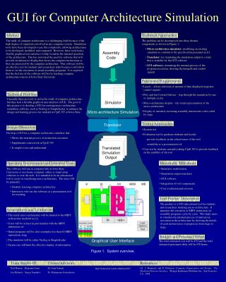
The four main core of undergraduate electronic engineering course can be considered as Electronics, Computer Application, Control and Communication. The objective of this research was the development of software approaches in teaching undergraduate Electronic Engineering Candidates to cover the practice of what and how Electronics, Computer Application, Control and Communication processes are going on. This paper describes a simple computer aided design approach for analysis of various system related to electronic engineering. The GUI design of this paper is mainly focus on teaching electronic circuits analysis, control system analysis and RFID antenna design. The simulation program for creating a GUI that linking sub program of each fields is developed using Matlab GUI. This paper is just a portion of the research "Design and Development of Easysuit Software Approaches for Electronic Engineering Subjects using Matlab. All performance result of a sample GUI program that students can use to analyse the behavior of circuits, control and communication systems. Dr. Wai Phyo Aung "Simulation Approach with MATLAB GUI for Teaching Electronic Engineering Subjects" Published in International Journal of Trend in Scientific Research and Development (ijtsrd), ISSN: 2456-6470, Volume-2 | Issue-4 , June 2018, URL: https://www.ijtsrd.com/papers/ijtsrd15742.pdf Paper URL: http://www.ijtsrd.com/engineering/electronics-and-communication-engineering/15742/simulation-approach-with-matlab-gui-for-teaching-electronic-engineering-subjects/dr-wai-phyo-aung<br>

E N D
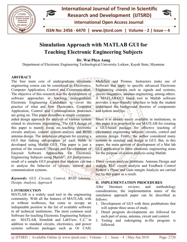
International Research Research and Development (IJTSRD) International Open Access Journal on Approach with MATLAB GUI for Teaching Electronic Engineering Subjects Teaching Electronic Engineering Subjects International Journal of Trend in Scientific Scientific (IJTSRD) International Open Access Journal ISSN No: 2456 ISSN No: 2456 - 6470 | www.ijtsrd.com | Volume 6470 | www.ijtsrd.com | Volume - 2 | Issue – 4 Simulation Approach with MATLAB GUI for Teaching Electronic Engineering Subjects on Approach with MATLAB GUI for Dr. Wai Phyo Aung Department of Electronic Engineering of Electronic Engineering Technological University Loikaw, Kayah State, Myanmar Loikaw, Kayah State, Myanmar MultiSim and Proteus. Instructors make use of Software that apply to specific advanced Elect Engineering courses such as signals and systems, electro magnetics, antenna engineering, among others. A MATLAB/GUI based tool in Matlab software provides a user-friendly interface to help the student understand the background theories of components and system analysis. Since it is already easily available in institutions, in this paper it is proposed to use MATLAB for creating a GUI-based package for effective teaching of electronics engineering subjects: circuits, control and antenna design. Firstly, the author considered many systems to simulate and design in GUI. But, in this paper, the main portion of development of a Mat lab GUI application in three electronic engineering areas for the purpose of system analysis using Matlab. Three system analysis problems: Antenna Design and analyis, RLC circuit analysis and Feedback Control System’s Phase and Gain margin Analysis are carried out by this paper as a result. II. IMPLEMENTATION PROCEDURES After literature reviews considerations, the implementation simulation approach paper can be described as follows: 1.Development of GUI with three pushbuttons that will seprate three areas of study. 2.Detail program developments are followed for each part of areas, antenna, circuit 3.Testing and redesigning m followed. ABSTRACT The four main core of undergraduate electronic engineering course can be considered as Electronics, Computer Application, Control and Communication. The objective of this research was the development of software approaches in teaching undergraduate Electronic Engineering Candidates to cover the practice of what and how Electronics, Computer Application, Control and Communication processes are going on. This paper describes a simple computer aided design approach for analysis of various system related to electronic engineering. The GUI design of this paper is mainly focus on teaching electronic circuits analysis, control system analysis and RFID antenna design. The simulation program for creating a GUI that linking sub-program of each fields is developed using Matlab GUI. This paper is just a portion of the research “Design and Development of Easysuit Software Approaches Engineering Subjects using Matlab”. All result of a sample GUI program that students can use to analyse the behavior of circuits, control and communication systems. Keywords: GUI, Circuits, Control, RFID antenna, Design, Analysis, Approach I. INTRODUCTION MATLAB is a widely used tool in the engineering community. With all the features of MATLAB, with or without toolboxes, has come to occupy an indisputable position in the list of available software in all technical institutions. The most common used Software for teaching Electronic Engineering Subjects are MATLAB, Simulink and LabView, C,C addition to standard circuits, electronics, and power systems software packages such as Or systems software packages such as Or CAD, The four main core of undergraduate electronic engineering course can be considered as Electronics, Computer Application, Control and Communication. research was the development of software approaches in teaching undergraduate Electronic Engineering Candidates to cover the practice of what and how Electronics, Computer Application, Control and Communication processes Instructors make use of Software that apply to specific advanced Electronic Engineering courses such as signals and systems, electro magnetics, antenna engineering, among others. A MATLAB/GUI based tool in Matlab software friendly interface to help the student understand the background theories of components a simple computer- aided design approach for analysis of various system related to electronic engineering. The GUI design of this paper is mainly focus on teaching electronic circuits analysis, control system analysis and RFID Since it is already easily available in institutions, in this paper it is proposed to use MATLAB for creating based package for effective teaching of electronics engineering subjects: circuits, control and tly, the author considered many systems to simulate and design in GUI. But, in this paper, the main portion of development of a Mat lab GUI application in three electronic engineering areas for the purpose of system analysis using Matlab. n program for creating a program of each fields is developed using Matlab GUI. This paper is just a portion of the research “Design and Development of Easysuit Software Approaches for for All performance Electronic Electronic result of a sample GUI program that students can use to analyse the behavior of circuits, control and analysis problems: Antenna Design and analyis, RLC circuit analysis and Feedback Control System’s Phase and Gain margin Analysis are carried GUI, Circuits, Control, RFID antenna, IMPLEMENTATION PROCEDURES After literature reviews implementation states of the simulation approach paper can be described as and and methodology methodology tool in the engineering community. With all the features of MATLAB, with or without toolboxes, has come to occupy an indisputable position in the list of available software in all technical institutions. The most common used Development of GUI with three pushbuttons that will seprate three areas of study. Detail program developments are followed for each part of areas, antenna, circuit and control. Testing and redesigning m-file program is c Engineering Subjects are MATLAB, Simulink and LabView, C,C++in electronics, and power @ IJTSRD | Available Online @ www.ijtsrd.com @ IJTSRD | Available Online @ www.ijtsrd.com | Volume – 2 | Issue – 4 | May-Jun 2018 Jun 2018 Page: 2720
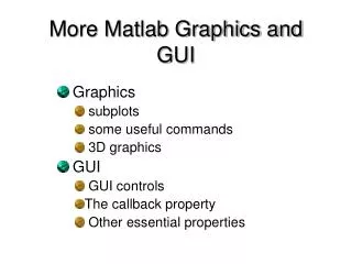
International Journal of Trend in Scientific Research and Development (IJTSRD) ISSN: 2456-6470 4.Conclusion, System Evaluation and Futurer Externsion processes are then done. A. Development of MATLAB GUI There are 5 steps in build the MATLAB GUI. First Use a MATLAB tool called guide (GUI Development Environment) to layout the components that shown in figure-1. This tool allows a programmer to layout the GUI, selecting and aligning the GUI components to be placed in it. Next is Use a MATLAB tool called the Property Inspector (built into guide) to give each component a name (a "tag") and to set the characteristics of each component, such as its color, the text it displays, and so on. After laying out the GUI component and set the property, the GUI will be look like in figure-2 for example according to the user creativity. And finally write code to implement the behavior associated with each callback function in m-files as shown in figure-3. A callback is a function that writes and associates with a specific GUI component or with the GUI figure which is often called event-driven programming. This last step is the difficult one and has to make an extra reading on how to write the coding before the GUI component can perform some task that user desire. Figure-3 Example of M-file for GUI B. Tasks in Simulation Program There are three tasks of m-file program in this paper, that are connected with GUI. The first task is the RFID antenna analysis and design. The second one is analysis of RLC circuit. The last one is Margin analysis of feedback control system. The code is to write controls how the GUI responds to events such as button clicks, slider movement, menu item selection, or the creation and deletion of components. This programming takes the form of a set of functions, called callbacks, for each component and for the GUI figure itself. A callback is a function that writes and associates with a specific GUI component or with the GUI figure. It controls GUI or component behavior by performing some action in response to an event for its component. This kind of programming is often called event-driven programming. The GUI figure and each type of component have specific kinds of callbacks with which it can be associated. The callbacks that are available for each component are defined as properties of that component. Each kind of callback has a triggering mechanism or event that causes it to be called. III. MATGUILABSIM FOR THE USER MatGUILabSim is referred to the GUI Package that the author design in this paper and User is referred to the students of mainly in undergraduate electronic engineering classes and their teachers. The following Figure-1 MATLAB GUIDE Layout After that, save the figure to a file. When the figure is saved, two files will be created on disk with the same name but different extents. The fig file contains the actual GUI that has been created, and the M-file contains the code to load the figure and skeleton call backs for each GUI element. These two files usually reside in the same directory. They correspond to the tasks of laying out and programming the GUI. When you lay out the GUI in the Layout Editor, your work is stored in the FIG-file. When you program the GUI, your work is stored in the corresponding M-file. Figure-2 Example GUI @ IJTSRD | Available Online @ www.ijtsrd.com | Volume – 2 | Issue – 4 | May-Jun 2018 Page: 2721
International Journal of Trend in Scientific Research and Development (IJTSRD) ISSN: 2456-6470 step by step consideration, design and implementation is done for this research paper. example, to pass the MATLAB variable time to my callback: time = datestr (now,0); s.BytesAvailableFcnMode = 'terminator'; s.BytesAvailableFcn={@mycallback,time}; We can specify the “callback” function as a string in the cell array. s.BytesAvailableFcn= {'mycallback',time}; The corresponding function header is: function mycallback(obj,event,time) B. Matlab GUI Development The GUI layout using “guide” and by chosing One texts, one axis and three push buttons for our desired GUI window, the layout become as shown in figure-4 as eclab.fig file. The m-file of this figure is as shown in figure-5. 1.Pre-consideration or study of Matlab background knowledge that will apply in this paper.(eg. Study about functions of matlab such as varargin, callback , etc). 2.Matlab GUI development. 3.Case study of each tasks: antenna design and analysis, RLC circuit analysis, Control system Phase/Gain margin analysis. 4.Functioning in GUI or functioning out from GUI with each m-file. 5.Overall GUI package recommendation. A. Study about functions of matlab Each component, and the GUI itself, is associated with one or more User-written routines known as callbacks. The execution of each callback is triggered by a particular user action such as a push button, mouse click, selection of a menu item, or the cursor passing over a component. We, as the creator of the GUI, provide these callbacks. All the processes (m- files) that we used for text, push buttons and/or panel, etc. are becom as a function of our main GUI m-file program. So, the functions such as varrargin need to be study before bulding a GUI. “varargin” maeans Variable length input argument list and it allows any number of arguments to a function. The variable “varargin” is a cell array containing the optional arguments to the function. For example, the function, function myplot (x,varargin) Plot (x,varargin{:}) collects all the inputs starting with the second input into the variable "varargin". MYPLOT uses the comma-separated list syntax varargin{:} to pass the optional parameters to plot. “handle” is a superclass of all handle classes. A handle is an object that indirectly references its data. When a handle is constructed, an object with storage for property values is created. The constructor returns a handle to this object. “Callback” functions require at least two input arguments. The first argument is the serial port object. The second argument is a variable that captures the event information. This event information pertains only to the event that caused the “callback” function to execute. For example, the function header for my callback is: function my callback (obj, event) We pass additional parameters to the callback function by including both the callback function and the parameters as elements of a cell array. For Figure-4 MatGUILabSim main window Figure-5 MatGUILabSim m-file For antenna analysis process, we study the demo script file and make linking the process to main GUI. Some parts of antenna analysis m-file type is shown in figure-6. The result of this desing process is shown in figure-7. For RLC circuit design, the rootlocus, LQR plot and Bode plot are used in m-file. The user can change R, L, C values and can analyse their result for system design. Some parts of RLC circuit m-file, @ IJTSRD | Available Online @ www.ijtsrd.com | Volume – 2 | Issue – 4 | May-Jun 2018 Page: 2722
International Journal of Trend in Scientific Research and Development (IJTSRD) ISSN: 2456 International Journal of Trend in Scientific Research and Development (IJTSRD) ISSN: 2456 International Journal of Trend in Scientific Research and Development (IJTSRD) ISSN: 2456-6470 fig file, the result plot are shown in figure figure-9. fig file, the result plot are shown in figure-8, and IV. CONCLUSION The Simulation Approach of GUI in the MATLAB environment has contributed to improved teaching and learning in Under Engineering Subjects by cases study, performance analysis and practicle testing processess. We will development various design analysis related systems and communications. The Simulation Approach of GUI in the MATLAB environment has contributed to improved teaching earning in Under-graduate Engineering Subjects by cases study, performance analysis and practicle testing processess. We will development various design analysis related to control Electronic Figure-6 Antenna m-file Figure-10 Margin Analysis m 10 Margin Analysis m-file Figure-7 The resuit of antenna design 7 The resuit of antenna design Figure-11 Margin Analysis Plot 11 Margin Analysis Plot Figure-8 The RLC circuit m- -file ACKNOWLEDGMENT Special Thanks are due to U Than Zaw Htwe,M.E(EP), Lecturer, EP Dept, YTU , for making me to be in touch with MATLAB Environment.The author would like to mention his thanks to all his partners from EcE Dept, TU(Loikaw) for their supports. REFERENCES 1.K.A.B ARIS,“Development Of Motor Control Using GUI,” Thesis, UNIVERSITY MALAYSIA PAHANG. 2.Ali H. Assi, Maitha H. Al Shamisi and Hassan A. N. Hejase (2011). MATLAB GUI Application for Teaching Electronics, Eng Research Using MATLAB, Dr. Ali Assi (Ed.), ISBN: 978-953-307-656-0. 3.http://www.mediafire.com/?qyttwdky110 http://www.mediafire.com/?qyttwdky110 For margin analysis of a feedback control system are done also with m-file and callback to main GUI. The m-file and result plot are shown in figure figure-12. For margin analysis of a feedback control system are file and callback to main GUI. The file and result plot are shown in figure-11 and Special Thanks Htwe,M.E(EP), Lecturer, EP Dept, YTU , for making me to be in touch with MATLAB Environment.The author would like to mention his thanks to all his Dept, TU(Loikaw) for their are due to U Than Zaw K.A.B ARIS,“Development Of Motor Control Using GUI,” Thesis, UNIVERSITY MALAYSIA Ali H. Assi, Maitha H. Al Shamisi and Hassan A. N. Hejase (2011). MATLAB GUI Application for Teaching Electronics, Engineering Education and Research Using MATLAB, Dr. Ali Assi (Ed.), 0. Figure-9 RLC circuit analysis figure 9 RLC circuit analysis figure @ IJTSRD | Available Online @ www.ijtsrd.com | Volume @ IJTSRD | Available Online @ www.ijtsrd.com | Volume – 2 | Issue – 4 | May-Jun 2018 Jun 2018 Page: 2723