Download
1 / 13
130 likes | 326 Views
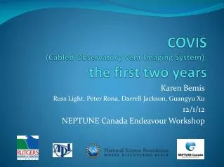
COVIS (Cabled Observatory Vent Imaging System): the first two years. Karen Bemis Russ Light, Peter Rona, Darrell Jackson, Guangyu Xu 12/1/12 NEPTUNE Canada Endeavour Workshop. COVIS is at the Endeavour site on the NEPTUNE Canada Observatory showing cable system.

E N D
COVIS (Cabled Observatory Vent Imaging System): the first two years Karen Bemis Russ Light, Peter Rona, Darrell Jackson, Guangyu Xu 12/1/12 NEPTUNE Canada Endeavour Workshop
COVIS is at the Endeavour site on the NEPTUNE Canada Observatory showing cable system.
COVIS’s beam coverage over the bathymetry of the Grotto vent cluster in the Main Endeavour Field. MEF instrument site Depth (m) Distance (m) Distance (m) COVIS North Tower
The COVIS system The sonar sits atop a 4 m tripod platform with 3 motors to control orientations Products • 3D images of plume(s) • Plume bending characterization • Vertical velocity and volume flux • Maps of diffuse flow distribution
Products of the basic software turned over to NEPTUNE Canada plume quick look diffuse flow quick look Bathymetry from MBARI 2008 cruise thanks to D. Clague.
Preliminary estimates of plume bending Periodogram of Angles Estimating the plume centerline uses Gaussian fitting on horizontal slices The centerline inclination (bending from vertical) and declination (compass direction of bending) vary over time by Guangyu Xu Declination Inclination by Jeff Rabinowitz
Spectral analysis of the plume bending data and the currents from RSN-N support both tidal and other forcing. Plume bending Plume bending Spectrum • Dominant (blue) peaks in plume bending angle spectrum match ambient currents and modeled semi-diurnal tides. • One secondary peak may be found in ambient current as well; another is unique to the plume. • Best explanation of secondary peaks is rift valley inflow Ambient current Across Rift Valley Along Rift Valley Pressure Thomson et al, 2005 JGR data from S. Mihaly
Changes in plume bending patterns 2010 2010 2011
COVIS mapping mode focuses on detecting regions with diffuse flow based on decorrelation. spatial distributions of diffuse flow change in area over time a map by Peter Lin, undergraduate intern, summer 2011
Diffuse flow influenced by tidal cycle: searching for mechanisms 2011-2012 area estimates Strong semi-diurnal peak 250 Area (m2) 0 10/2/11 1/1/12 Time (days) Oct 2010 area estimates But not in Oct 2010. why? 220 Area (m2) 0 10/1/10 Time (days) 10/26/10
The Doppler mode quantifies vertical flow rates and estimates volume flux. preliminary analyses • detection of plumes • estimation of vertical velocity and volume flux Mean Volume Flux Mean Vertical Velocity
volume flux2010 to 2012 Plume Over North Tower Plume Over In-Situ Site