Download
1 / 1
10 likes | 174 Views
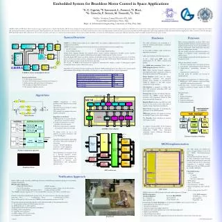
PMSM Motor. Position signals and motor current conditioning. FPGA Board. Motor driver. A/D converter. Task. manager. TASK. synchronization. to hardware. one. high. low. shot. priority. priority. high. low. one. priority. priority. shot. high. low. priority. priority.

E N D
PMSM Motor Position signals and motor current conditioning FPGA Board Motor driver A/D converter Task manager TASK synchronization to hardware one high low shot priority priority high low one priority priority shot high low priority priority Embedded System for Brushless Motor Control in Space Applications *G. C. Caprini, #F. Innocenti, L. Fanucci, #S. Ricci,#G. Taraschi, P. Terreni, M. Tonarelli, #L. Tosi *Galileo Avionica, Campi Bisenzio (FI), Italy #Cesvit Microelettronica, Prato, Italy Dept. of Information Engineering, University of Pisa, Pisa, Italy AMBRA(ASIC for BRushless Motor control in space Applications)isa Multi Chip Module (MCM) devicedesigned for high performance synchronous brushless motor control in space applications. Brushless motors are used in space applications for their simple and robust construction, high power output to weight ratio, low inertia and optimal performances at high and low speed. Typical applications are scan mirror, thrust vector control actuators, fuel valve control actuators, solar array deployment, control moment gyroscopes, high and low RPM applications, light weight applications and low thermal emission applications. Motor control is achieved through a DSP-based fully digital ASIC architecture. This solution provides, with respect to typical mixed analog-digital control systems, higher flexibility, cost reduction, drift elimination and greater radiation robustness which are highly required features in space systems. System Overview Hardware Firmware AMBRA is a MCM system made up of a digital ASIC, two analog to digital converters, a four double channels multiplexer and a ROM. AMBRA system communicates with external devices by an analog interface and some digital ones: • encoder interface • serial interface •inverter bridge interface • input/output digital interface System block diagram includes the required motor control external components: brushless motor, position transducer, position sensor signal conditioning, current signal conditioning and 3-phase inverter. The fully digital ASIC carries out all the functions for brushless motor control, the system acquires two of the three motor currents and relative position transducer signals and it provides PWM (Pulse Width Modulation) signals to drive the 3‑phase inverter to reach the final motor position. Two 12 bit - 10 MSPS A/D converters are required to simultaneously sample a couple of homogenous signals coming from motor current and position sensor. The ASIC architecture was developed as a trade-off between performance, complexity and flexibility. To ease ASIC testability a fully synchronous approach was pursued. ASIC circuit includes the following devices: 16 bit - fixed point DSP macro cell characterized by 10 MIPS computational power; Two RAM data memories 256x16 and a RAM program memory 2048x16; FOC (Field Oriented Control) equipment unit implements direct and inverse Clarke & Park transformation for PID calculation; Serial Interface block, used for debug, performance evaluation and program memory boot, includes an asynchronous UART in addition to the DSP internal synchronous serial interface; AD interface is engaged in reading data from AD converter, controlling ADC and data compensation; Timing Unit produces all timing references necessary for AMBRA system operation, (resolver, A/D acquisition, Clarke & Park conversion and PI calculation); Register Block interfaces the DSP core with the rest of the circuit; we have three kind of registers: Setup, Operational and Special; Space Vector is in charge of controlling the generation of the PWM channels; PWM unit generates the signals for driving the MOSFET gates of the inverter bridge. The Encoder block interfaces an external incremental encoder • Rotor position elaboration, position PID control • function and FOC reference current generation are • implemented in firmware by the selected DSP core. • To ease maintenance each functionality has been • derived as independent module. • We can modify, activate or deactivate modules to • change or to improve system functionality and • performances. • A task manager oversees all module operations in a • preemptive mode. • We have three kind of module: • 1. One shot : executed once or in special situations • Low priority : performing not critical functions • 3. High priority : performing functions of vital • importance for system activity. • For each group the modules are executed in • circular priority. • The modules are divided into two different cycles: • 1. PWM cycle : FOC calculates signals for PWM • and MOS commands are generated . • Resolver cycle : resolver excitation waveform period it contains an integer number of PWM cycles. • Developed tasks : • 1. Filter • 2. Position calculation • 3. PID controller • 4. Trajectory calculation • 5. Serial communication Algorithms are partitioned between hardware and firmware (DSP) implementations according to the required speed performances, their criticality and flexibility (for instance to cope with possible new system requirements). A.M.BR.A. system and peripheral devices System requirements: •2-3 kHz current control band •21.8 kHz FOC (Field Oriented Control) work frequency •3.6 kHz position and speed loop work frequency •100 ns analog to digital time conversion •12 bit analog to digital resolution. Algorithms AMBRA implements a motor position control based on two nested closed loops. The inner loop is in charge of current and torque controls. The external loop manages the motor position and speed. Algorithms considered: 1. PID algorithm to increase dynamic performance in position control. 2. Trajectory generation to control brushless rotor movement. 3. Position computation to calculate rotor position from resolver data. To reduce errors we use a not uniform 16 points correlation with 3,5 bit ENOB gain. Algorithms performances, depending on resolver kind, with multispeed x1 x8 resolver: accuracy : 0.10625 millidegrees resolution < 0.125 millidegrees precision : 0.0075 millidegrees These algorithms are managed as task in a real-time operative system. Several algorithms, not concurring to achieve request performances, are implemented in firmware (serial communication, tasks management algorithms etc.) PID controller To improve transportability all the hardware blocks have been described in technology-independent VHDL (Very high-speed integrated circuits Hardware Description Language) code. A.M.BR.A. block diagram Firmware modules scheduling MCM implementation Position computation algorithm The ASIC design was finalized by means of logic synthesis for the 0.35 µm CMOS Austriamicrosystems technology. The rationale behind this choice is: to allow technology access through reduced price multi-project wafer and to reduce risks in case of technology retargeting to a radiation tolerant technology (0.35 µm CMOS provided by ATMEL (MH1RT)). Sampling scheme ASIC architecture Final chip features: • 144 Pads - 67 inputs - 47 outputs - 30 power supply pads • PAD limited • Area : 19.901 mm2 • Clock frequency : 20 MHz • Power consumption : 226.3 mW @ 3.3 V •Fault coverage greater than 97% Verification Approach • Before ASIC foundry run, the overall design has been verified through rapid prototyping on a customarily designed breadboard. • Breadboard components: • • Xilinx XC2V4000 FPGA • RS232 interface • • two A/D converters • permanent magnet 3-phase motor with resolver • • 3 phase MOS bridge with relative driver • analog interface modules • The AMBRA circuitry required 33% of the overall FPGA resources (13% due to the DSP core). • Several test have been implemented: system test of PI control current evaluating step response • rise time : 90 µs settling time : 700 µs current band : 2.8 kHz • With a multi-speed (x1 x8) resolver the AMBRA position precision amounts to 19 bit. ASIC layout MCM is built on 1.6 FR4 substrate with tracks and isolations of 100 µm. MCM components : • 12-Bit A/D converter • 10 MSPS (tconv < 50 ns) • space qualified • 28 pin DIL - die Rad-hard 8Kx8 PROM space qualified 28 pin flatpack - die Analog multiplexer 4:1 - 2 channels space qualified - die • Proper test vectors have been developed to verify the functionality of the prototyped system. • test program loading into DSP program memory; • DSP initialization of ASIC registers; • (iii) particular position and current values simulation; • (iv) DSP position computation; • (v) full FOC cycle execution; • (vi) DSP reading of FOC cycle results; • (vi) computed values verification. Summarizing, the main advantages of the presented AMBRA motor control system are: • great reduction in the number of devices • size and cost reduction • radiation/temperature/aging robustness • increase in the overall reliability due to the fully digital approach • higher system flexibility • reduced design time/efforts • system re-use in many other applications based on actual position sensor (sine/cosine encoder) Breadboard Caprini P151/MAPLD 2004 Embedded System for Brushless Motor Control in Space Applications *G. C. Caprini, #F. Innocenti, L. Fanucci, #S. Ricci,#G. Taraschi, P. Terreni, M. Tonarelli, #L. Tosi *Galileo Avionica, Campi Bisenzio (FI), Italy #Cesvit Microelettronica, Prato, Italy Dept. of Information Engineering, University of Pisa, Pisa, Italy This paper presents a Multi Chip Module (MCM) device, named AMBRA(ASIC for BRushless Motor control in space Applications), designed for high performance synchronous brushless motor control in space applications. This kind of motors are used for their simple and robust construction, high power output to weight ratio, low inertia and optimal performances at high and low speed. Typical applications are scan mirror, thrust vector control actuators, fuel valve control actuators, solar array deployment, control moment gyroscopes, high and low RPM applications, light weight applications and low thermal emission applications. Motor control is achieved through a DSP-based fully digital ASIC architecture. This solution provides, with respect to typical mixed analog-digital control systems, higher flexibility, cost reduction, drift elimination and greater radiation robustness which are highly required features in space systems. System Overview Hardware Firmware AMBRA is a MCM system made up of a digital ASIC, two analog to digital converters, a four double channels multiplexer and a ROM. AMBRA system communicates with external devices by an analog interface and some digital ones; in particular encoder, serial, inverter bridge and input/output digital interfaces are present. Figure 1 shows the system block diagram including the required motor control external components: obviously brushless motor, position transducer, position sensor signal conditioning, current signal conditioning and 3-phase inverter providing the required power levels for the brushless motor. The system acquires two of the three motor currents and relative position transducer signals and it provides PWM (Pulse Width Modulation) signals to drive the 3‑phase inverter. This kind of system calls for the follow system requirements: · 2-3 kHz current control band · 21.8 kHz FOC (Field Oriented Control) work frequency · 3.6 kHz position and speed loop work frequency · 100 ns analog to digital time conversion · 12 bit analog to digital resolution. Implemented algorithms are partitioned between hardware and firmware (DSP) implementations according to the required speed performances, their criticality and flexibility (for instance to cope with possible new system requirements). For an high updating frequency of control ring the maximum pass band amplitude is required. To this aim current control function are implemented in hardware. High resolution PWM (Pulse Width Modulation) signals generator and serial communication interfaces are implemented in hardware too. Position/speed extraction and PID (Proportional Integral Derivative) controller are implemented in software because requires less velocity but more flexibility. The MCM system exchanges data with the external world through a serial communication interface. The fully digital ASIC carries out all the functions for brushless motor control generating 3 PWM channels for driving the MOSFET gates of the inverter bridge to reach the final motor position. The latter is input to the ASIC from the external world through a serial interface. Two 12 bit - 10 Msps A/D converters are required to simultaneously sample a couple of homogenous signals coming from motor current and sine/cosine signal from the two multispeed resolver winding of the position sensors . The ASIC architecture, shown in figure 2, was developed as a trade-off between performance, complexity and flexibility. Besides, to ease ASIC testability, which is of paramount importance in space application, a fully synchronous approach was pursued with the exception of the RAMs (Random Access Memories) control logic operating on both clock edges. ASIC circuit includes a 16 bit - fixed point DSP macro cell. This DSP is characterized by 10 MIPS computational power which is more than enough with respect to the figure (about 7 MIPS) required to perform all the aforementioned operations, particularly position control and trajectory generation. 70% of DSP resources are involved in cyclic activity, 23% for reference generation, 46% for actual position and speed calculation and 31% for feed forward PID control), the rest are used in acyclic activity. Two RAM data memories 256x16 and a RAM program memory 2048x16 are included. A FOC (Field Oriented Control)[1,2]equipment unit implements direct and inverse Clarke & Park transformation for PID calculation, it comprises the control current ring implementing in hardware current PI control and motor vectorial control algorithm . FOC unit is made up of a sequencer, a 16-bit signed multiplier, an 32-bit signed adder and sequential logic. The Serial Interface block in Fig. 2, used for debug, performance evaluation and program memory boot, includes an asynchronous UART in addition to the DSP internal synchronous serial interface. An AD interface is engaged in reading data from AD converter, AD converter controlling ADC and data compensation adding an adjust value. A Timing Unit produces all timing references necessary for AMBRA system operation, in particular resolver, A/D acquisition, Clarke & Park conversion and PI calculation. The Register Block in Fig. 2 interfaces the DSP core with the rest of the circuit; we have three kind of registers: Setup (writeable by hardware and readable by software), Operational (R/W by hardware at high priority and R/W by software at low priority) and Special. Special registers are seen as simple registers but they perform most complex functions as sine, cosine, arctangent and 32 bit division. Both software and hardware writes them synchronously. Space Vector is in charge of controlling the generation of the PWM channels (A, B and C). It’s made up of a sequencer, a 16-bit signed multiplier, a 32-bit signed adder, sequential logic and 32 bit divisor.PWM unit generates the signals for driving the MOSFET gates of the inverter bridge (A, B and C channels). By this unit MOS driving polarity can be inverted . The Encoder block interfaces an external incremental encoder which is the most used feedback for high performance control systems. This interface core is a 16 bit quadrature up-down counter which coverts 2 quadrature signals coming, from an external squaring circuit for sine/cosine encoder or directly from a TTL encoder, in a parallel word used by the algorithms To improve transportability all the hardware blocks have been described in technology-independent VHDL (Very high-speed integrated circuits Hardware Description Language) code. Rotor position elaboration, position PID control function and FOC reference current generation are implemented in firmware by the selected DSP core. To ease maintenance each functionality has been derived ad independent module. We can modify, activate or deactivate modules to change or improve system functionality and performances. A task manager oversees all module operations in a preemptive mode; figure 4 shows the firmware modules scheduling. We have three kind of module: (i) One shot : executed once or in special situations; (ii) Low priority : performing not critical functions (iii) High priority which performs functions of vital importance for system activity. For each group the modules are executed in circular priority. The modules are divided into two different cycles, in PWM cycle FOC calculates signals for PWM and MOS commands are generated while Resolver cycle is the resolver excitation waveform period and it contains an integer number of PWM cycles. The developed task are: (i) Filter, for resolver signal filtering, improves signal to noise ratio to increase significant bits number; (ii) Position calculation, the most critical task because directly influences position accuracy; (iii) PID controller guides system response to external stimulus; (iv) Trajectory calculation is an optional task to drive motor trajectory during movement; (v) Serial communication manages protocol between controller and host system. These modules are synchronized as Figure 6 shows.  Algorithms As showed in figure 1, AMBRA implements a motor position control based on two nested closed loops. The inner loop is in charge of current and torque controls while the external loop manages the motor position and speed. To this aim, several algorithms have been considered: (i) PID algorithm to increase dynamic performance in position control; proportional, integral and derivate constants can be fixed by serial interface to ease system set-up. (ii) trajectory generation to control brushless rotor movement (iii) position computation to calculate rotor position from resolver data. The latter being the most critical for the overall system performance. Figure 2 shows implemented architecture for this algorithm using a multispeed x1 x8 resolver. Input data ENOB (effective number of bit), offset errors and gain mismatch of analog chain highly affect position calculation accuracy. To reduce errors we use an algorithms based on signal oversampling not introducing phase lag, in particular a not uniform 16 points correlation with 3,5 bit ENOB gain. Algorithms performances, depending on resolver kind, are been evaluated in terms of accuracy, precision and resolution. With multispeed x1 x8 resolver we have an accuracy of 0.10625 millidegrees, a resolution less then 0.125 millidegrees and a precision of 0.0075 millidegrees These algorithms are managed as task in a real-time operative system. Several algorithms, not concurring to achieve request performances, are implemented in firmware, for example serial communication and tasks management algorithms. Conclusions Verification Approach Before ASIC foundry run, the overall design has been verified through rapid prototyping on a customarily designed breadboard; figure 5 shows the breadboard block diagram. The latter features a Xilinx XC2V4000 FPGA, a RS232 interface, two A/D converters, a permanent magnet 3-phase motor with resolver, a 3 phase MOS bridge with relative driver and analog interface modules. The AMBRA circuitry required 33% of the overall FPGA resources (13% due to the DSP core).Several test have been implemented, for example a system test of PI control current evaluating step response gives a rise time of 90 μs, a settling time of 700 μs and a current band 2.8 kHz which satisfied the request performances. Proper test vectors have been developed to verify the functionality of the prototyped system. In particular we executed: (i) test program loading into DSP program memory; (ii) DSP initialization of ASIC registers; (iii) particular position and current values simulation; (iv) DSP position computation; (v) full FOC cycle execution; (vi) DSP reading of FOC cycle results; (vi) computed values verification. The same will be applied to the final system featuring the AMBRA ASIC when back from the silicon foundry. After the successful verification of the breadboard prototype, the ASIC design was finalized by means of logic synthesis for the 0.35 μm CMOS Austriamicrosystems technology. The rationale behind this choice is to allow technology access through reduced-price multi-project wafer and at the same time reduce risks in case of technology retargeting to a radiation tolerant technology such as the 0.35 µm CMOS provided by ATMEL (MH1RT). The final chip, whose layout is shown in Fig. 7, has 144 PADs; 67 inputs, 47 outputs and 30 power supply PAD (15 Vcc – 15 Gnd). The chip resulted to be PAD limited with an overall area of 19.901 mm2, a clock frequency of 20 MHz and an estimated power consumption of 226.3 mW @ 3.3 V power supply. Fault coverage is greater than 97%. MCM is built on 1.6FR4 substrate with tracks and isolations of 100 μm. It’s build up of a space qualified 12-Bit A/D converter in die mounted in a 28-pin DIL (Dual-in-Line) package, with 10 MSPS power computation, conversion time less then 50 ns; a space qualified analog multiplexer 4:1 - 2 channels in die and space qualified Rad-hard 8Kx8 PROM in die mounted in a 28 pin flatpack. System accuracy performances depend on the kind of used resolver. In the prototyping breadboard where we adopted a multi-speed (x1 x8) resolver, the AMBRA position precision amounts to 19 bit. Summarizing, the main advantages of the presented AMBRA motor control system are: (i) great reduction in the number of devices and consequent size and cost reduction; (ii) increase in the overall reliability due to the fully digital approach; (iii) radiation, temperature and aging robustness; (iv) higher system flexibility and reduced design time/efforts due to a DSP-core based system. Particularly, the latter allows system re-use in many other applications based on actual position sensors (sine/cosine encoder).