Download
1 / 24
240 likes | 364 Views
This paper presents a comprehensive framework for the design and synthesis of multiprocessor embedded applications, focusing on the co-design methodology that integrates hardware and software components. It discusses a modeling and simulation infrastructure, hardware-software co-design processes, and the co-simulation of various models. The approach emphasizes object-oriented specification and multi-paradigm modeling to foster efficient design environments. The paper also includes practical examples and remarks on the importance of synthesis in ensuring effective design realization across dedicated and off-the-shelf processors.

E N D
System Synthesis for Multiprocessor Embedded Applications UFRGS Informática Flávio R. Wagner Marcio Oyamada Luigi Carro Marcio Kreutz Universidade Federal do Rio Grande do Sul Porto Alegre, Brazil DATE´2000, Paris, Frande, March 2000 UFRGS
Outline 1. Introduction 2. Modeling and simulation infra-structure 3. Hardware-software co-design methodology 4. Co-simulation 5. Example 6. Synthesis 7. Final remarks
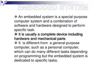
1. Introduction • embedded electronic systems: control of physical processes and equipments • target architecture • off-the-shelf or dedicated processors (DSP, RISC, microcontrollers) • software • dedicated analog and digital hardware • requirements for a design environment • appropriate specification mechanisms for various abstraction levels • stepwise refinement process • co-simulation
Motivation • existing approaches for design environments • single language / computation model for high-level specifications • multi-language environments • object-oriented design • our solution combines benefits from all these approaches • object-oriented specification and simulation • single environment for the whole design process • various types of models are possible • single, high-level abstract specification • computation model: procedural, state machines • co-specification and co-simulation: discrete, analog, VHDL
2. Modeling and simulation infra-structure SIMOO environment • object-oriented modeling and simulation of discrete systems • multiparadigm modeling • each object in the model may follow a different paradigm • paradigm is a combination of aspects for the behavior description • visual interactive simulation • graphical description of the static structure • behavior described in C++ or state diagrams annotated with C++ • simulation library implements the multiple paradigms
SIMOO: software architecture Model Editor Tool C++ code executable code compiler library of autonomous objects SIMOO class library • default user interface automatically added to all models • querying models, tracking and steering experiments • • interface objects • • visualization of results, data collection, interactive data input
3. Hw-sw codesign methodology • initial abstract specification • C++ or state diagrams annotated with C++ • objects corresponding to the physical world may be modeled by a continuous behavior • design proceeds through a stepwise refinement • hierarchical refinement: same abstraction level • abstraction refinement: design decisions are taken • abstract objects are mapped into objects of a target architecture • digital or analog hardware, software • validation of all possible models by co-simulation
Library-based synthesis • selection of hardware objects from a previously built library of classes for the possible target architectures • digital hardware objects previously described in VHDL • no automatic synthesis from C++ to VHDL • software objects may be automatically generated from the abstract specification • from C to assembly languages of the selected processors
4. Co-simulation • co-simulation for the validation of the initial specification • discrete behavior - algorithms or state diagrams • continuous behavior - physical environment • co-simulation for the validation of possible implementations • discrete behavior - algorithms or state diagrams • for parts that have not been yet refined • for software parts • continuous behavior • for the physical environment • for analog hardware • VHDL • for digital hardware
Coupling SIMOO and VHDL SIMOO simulator VHDL simulator
Coupling SIMOO and VHDL • interfaces in both domains are automatically generated • C-file in the VHDL domain • interface object in the SIMOO domain • interfaces are responsible for ... • communication - exchange of data and format conversion • synchronization between simulators • conservative approach • communication between simulators by sockets • distributed simulation is possible • SIMOO currently runs on Windows • VSS runs on Unix workstations
Hybrid discrete-continuous simulation • objects with analog behavior • modeled by a set of differential equations • implement the numerical integration method • object attribute defines integration time step • signal-flow approach • mathematical functions from inputs to outputs • appropriate for objects that ... • don´t have a physical implementation yet • model the physical environment • are modeled at a higher abstraction level than basic components (PID controllers, converters, filters)
Hybrid discrete-continuous simulation • current situation • differential equations directly described in C++ • integration time step must be defined by the programmer • scheduling the execution of analog objects • if there are more than one AO and they communicate with each other, they must be scheduled at each time step and exchange messages • if not, an AO may be scheduled at intervals that depend on the discrete objects and then execute several integration steps • future work • better modeling environment • better time advancement mechanism, including automatic time step definition • integration with Matlab / Simulink
5. Example • benchmark for specification of heterogeneous systems • physical plant: crane with a load, moving along a track • control • assures smooth movement, without bumps and oscillations • verifies if displacement does not exceed limits and if angle of the load is acceptable (emergency break) • auto-test of sensors
First modeling of the crane physical plant controls car movement, sensor checking, output forces to Actuators drives the dc motor (speed), control breaks and emergency break checks plausibility of car position and load angle
First modeling of the crane • physical plant Plant_rk is an object with continuous behavior • all other objects have discrete behavior • M_Control combines two computation models • control algorithm for movement is a discrete computation of the state-variable method q n+1=A*q n + B*[Motor_Voltage Car_Position]T at each 10 ms • sensor checking is an FSM • Diagnosis is an FSM • Actuators is an algorithm
Second modeling of the crane M_Control split into two objects FSM for sensor checking main control algorithm, arithmetic operations
Third modeling of the crane FSMs (Job_Control and Diagnosis) merged into a single object to be implemented as digital hardware and modeled in VHDL
6. Synthesis • library of previously characterized processors • characterization by attributes size of binary word types of instructions memory operand addressing modes execution time (in clock cycles) of each instruction number of busses to access memory type of memory number of registers use of pipeline and depth of eventual pipeline use of harvard architecture • current library: C25, 8051, RISCO
Characterizing the application application is characterized as: - data-dominated - memory-dominated - control-dominated C++ CDFG machine- independent 3-address code M P APP = APM = P + M + C P + M + C C APC = P + M + C machine-independent code is fitted to each type of processor architecture: RISC, DSP, microcontroller
Selecting the processor • performance profiles measure, for the given application, the relative cost of the processor for each aspect (data, control, memory) • selection algorithm • analyzes the application and performance profiles • chooses the processor best suited for the application • currently: measure of the mean geometric distance between the desired application profiles and the performance profiles Pi PPPi = Pi + Mi + Ci Mi PPMi = Pi + Mi + Ci Ci PPCi = Pi + Mi + Ci
Selecting the processor examples from the crane modeling Control Processor APM APC APP PPM PPC PPP Distance 8051 0.304 0.298 0.396 0.329 0.213 0.456 0.107 RISCO 0.184 0.350 0.464 0.098 0.624 0.277 0.342 C25 0.001 0.430 0.568 0.084 0.700 0.214 0.452 Multiplication Processor APM APC APP PPM PPC PPP Distance 8051 0.543 0.157 0.299 0.091 0.070 0.838 0.708 RISCO 0.301 0.240 0.457 0.029 0.497 0.473 0.374 C25 0.006 0.342 0.651 0.019 0.664 0.315 0.465
7. Final remarks • SIMOO is used as a high-level modeling and verification front-end • co-simulation: SIMOO used as a seamless environment for validating both high-level designs and implementations • stepwise refinement: progressive replacement of abstract descriptions by implementation descriptions • synthesis • target architecture is a multiprocessor platform • semi-automatic selection of the processors that best match the desired design requirements for the given objects
Future work • basic modeling and simulation infra-structure • optimize the hybrid modeling and simulation mechanisms • distributed simulation with an optimistic protocol • multi-language approach: integrate other languages • synthesis • communication synthesis • find optimal selection algorithms and consider other requirements (cost, area, power) • explore partitioning of objects into processors • model larger examples where multiprocessor platforms are needed