Download
1 / 31
310 likes | 569 Views
IMPACT/SEP Thermal Design John Hawk, GSFC John.P.Hawk@nasa.gov (301)-286-2754. SEP Thermal Presentation Outline. Thermal Requirements Thermal Environment Thermal Model Instrument Interfaces Temperature Limits Thermal Cases Thermal Design MLI Radiators Coatings Temperature Predictions

E N D
IMPACT/SEP Thermal DesignJohn Hawk, GSFCJohn.P.Hawk@nasa.gov(301)-286-2754 TvR
SEP Thermal Presentation Outline • Thermal Requirements • Thermal Environment • Thermal Model • Instrument Interfaces • Temperature Limits • Thermal Cases • Thermal Design • MLI • Radiators • Coatings • Temperature Predictions • Conclusions TvR
Component Interface Requirements • Spacecraft operational panel interface temperature range of -13C to +45C • Spacecraft survival panel interface temperature range of -18C to +50C • Components are thermally isolated on brackets • Components are thermal blanketed at spacecraft interface TvR
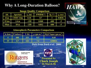
STEREO Thermal Environment Early Orbit: Ahead Spacecraft: Maneuvers for up to first 60 days can off-point from sun-pointing by up to 45 degrees for up to 105 minutes (single lunar swing-by) Behind Spacecraft: Maneuvers for up to first 90 days can off-point from sun-pointing by up to 45 degrees for up to 105 minutes (two lunar swing-bys) Extreme mission orbit conditions: Ahead S/C: Perihelion = 0.879 AU, Aphelion = 1.040 AU Behind S/C: Perihelion = 0.960 AU, Aphelion = 1.131 AU Nominal orbit: Ahead S/C: Perihelion = 0.943 AU, Aphelion = 0.979 AU Behind S/C: Perihelion = 1.003 AU, Aphelion = 1.083 AU TvR
Environmental Heat Inputs • Incident Solar Flux Determined by Spacecraft Perihelion and Aphelion • Solar Flux at 1 AU: 1366.5 W/m2 Ahead S/C Extreme Solar Flux Perihelion 0.879 AU 1768.6 W/m2 Aphelion 1.040 AU 1263.4 W/m2 Behind S/C Extreme Solar Flux Perihelion 0.960 AU 1482.7 W/m2 Aphelion 1.131 AU 1068.3 W/m2 TvR
Ahead And Behind Thermal Models Ahead Behind TvR
Instrument To Spacecraft Interface • SEP Central Electronics Isolated: • 6 Fasteners = 0.065 W/°C • Grounding Strap = TBD W/°C • TOTAL > 0.05W/°C • Studying alternate attachment configurations • SIT Electronics Isolated: • 4 Fasteners = 0.039 W/°C • Grounding Strap = TBD W/°C • TOTAL < 0.05W/°C • SEPT-E/SEPT-NS Isolated: • 4 Fasteners = 0.039 W/°C • Grounding Strap = TBD W/°C • TOTAL < 0.05W/°C TvR
Thermal Cases • On Station • Operational Hot • Ahead and Behind • Operational Cold • Ahead and Behind • Survival Hot • Ahead and Behind • Survival Cold • Ahead and Behind • 45° Off-Pointing Cold (Instruments Shaded For 105 Minutes) • Ahead and Behind • 45° Off-Pointing Hot (Sun On Instruments Radiators For 105 Minutes) • Ahead and Behind TvR
Early Orbit Thermal Case Assumptions • All Aperture Doors Closed Until After All Maneuvers • Instruments At Operational Temperatures With Doors Closed Until Immediately Prior To 45 Degree Off-pointing • Solar Flux at 1 AU: 1366.5 W/m2 • BOL Optical Properties • Worst Case Cold • Instruments Shaded For 105 Minutes • Worst Case Hot • Sun On Instruments Radiators For 105 Minutes TvR
Thermal Blankets • ITO coated silver conductive composite (Goddard Composite) deposited on Kapton • Goddard Composite Outer Layer Blanket to be coated by GSFC • 10-18 layer except at tight bends (~ 600 g/m^2) • MLI to be fabricated by APL per GSFC designs Effective Emittance (e*) 0.05 - 0.02 Optical Properties a(bol) e(bol)a(eol) e(eol) 0.1 0.68 0.2 0.64 TvR
Thermal Blanket Alternatives • Goddard Composite deposited on Aluminum or Stainless Steel Substrate • Additional Mass • Electrical Conductivity Requirement Not Yet Tested • Aluminum Grid Deposited On Goddard Composite • Lower Emissivity • Additional Mass • Electrical Conductivity Requirement Not Yet Tested TvR
Thermal Coatings Optical Properties a(bol) e(bol)a(eol) e(eol) 0.1 0.68 0.2 0.64 0.97 0.89 0.97 0.89 0.2 0.92 0.45 0.89 ITO Goddard Composite MSA94B Black Paint NS43C White Paint TvR
Radiators • ITO Silver Conductive Composite Coating • Deposited on Kapton and Bonded to Aluminum or Deposited Directly on the Aluminum • NS43C White Paint • Painted Directly on SEPT TvR
Heater Sizing • Operational heaters sized at 75 % duty cycle at 30.5 V • Instrument survival heaters sized for 100% duty cycle at 25 V TvR
INSTALLED HEATER POWER (Watts) Installed heater power results in max 75% duty cycle for operational heaters, 100% for survival heaters TvR
Ahead Spacecraft Operational Temperature Predicts Cold predictions with heater power TvR
Ahead Spacecraft Survival Temperature Predicts Cold predictions with heater power TvR
Behind Spacecraft Operational Temperature Predicts Cold predictions with heater power TvR
Behind Spacecraft Survival Temperature Predicts Cold predictions with heater power TvR
HEATER CIRCUIT DESIGN No Redundancy, Not Single Fault Tolerant • Survival Heaters • Thermostatically controlled • Operational Heaters • Thermostatically controlled • SIT • Microprocessor controlled • LET • SEP central • SEPT TvR
Component Level Thermal Analysis Methodology • Analyzing components dissipating more than 20 mW • Conformal Coating on boards e = 0.80 • Interior of Electronic boxes • Black Anodized • Black Paint • If the junction to case resistance, jc, unavailable used the value recommended by Mil-M-38510 • The first analysis considers only radiation from the component case • If the resulting temperature is unacceptable, conduction through the leads and/or bonding the component to the board should be considered TvR
Component Level Thermal Analysis Needed • SEP Central, SIT Electronics • Once final component layouts are identified, analyze each component to verify that the temperatures are within the derated limits • Verify junction to case resistances, jc, used in analysis meet manufacturers specifications TvR
Conclusions • SIT, SEPT-E, And SEPT-NS Aperture Doors Must Remain Closed Until After All Maneuvers • Instruments Should Remain Operational Until Immediately Prior To 45 Degree Off-pointing • -Instruments Potentially Completely Shaded • Full Sun On Lightweight Foils And Detectors Behind Open Aperture Doors During 12 Minute On Station Failure Mode • -Foil Temperatures Rise Rapidly In Sun TvR
Conclusions continued • Have Flown Detectors Configured Like The LET L1 Detectors Before But They Were On Spinning Spacecraft • Here We Have Some Detectors With Their Foils Staring At The Sun And Others Never Seeing The Sun • Foils Staring At The Sun Run As Much As 60 °C , Detectors Never Seeing The Sun Run As Cold As -106 °C • System Level Allocation Must Support Survival And Operational Heater Power? TvR
Future Work • Thermal Balance and Thermal Vacuum Test Planning • May Need Some Tests On The Foils To Make Sure That They Won't Break Due To Contraction When Going Cold • Additional Component Level Analysis • Verify case qualification temperatures TvR