Download
1 / 24
250 likes | 681 Views
Experiments Of SNG And DNG Metamaterials. 電機三 許宗堯. Outline. Introduction Bulk Metamaterials Thin-wire epsilode-negative metamaterials SRR array mu-negative metamaterials Rectangular Waveguide analysis Rectangular Waveguide in various materials. Introduction.

E N D
Outline • Introduction • Bulk Metamaterials • Thin-wire epsilode-negative metamaterials • SRR array mu-negative metamaterials • Rectangular Waveguide analysis • Rectangular Waveguide in various materials
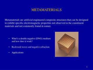
Introduction • Effective permittivity and effective permeability are basic engineering parameters of metamaterials • Contrary to the methods with plane-wave excitation, one may turn to the waveguide methods • the characterization of bulk SNG and DNG metamaterials in a waveguide environment • an investigation of the properties of a waveguide filled with a metamaterial as a new guiding structure
Introduction • The phasor form of electric and magnetic fields in lossy case • The imaginary part of permittivity and permeability is the loss of energy
Bulk Metamaterials • Thin-wire epsilon-negative metamaterials • It has been shown that an array of parallel wires exhibits a high-pass behavior for an incoming plane wave whose electric field is parallel to the wires • a<<λ, the array can be taken as continous plasma
Bulk Metamaterials • εreff,z denotes the effective relative permittivity in the z direction; fp is the the cutoff frequency of the array (“plasma frequency”) • The plasma frequency generally depends on the geometry of the system (a lattice constant and wire radius) • εreff,x ≈ 1, εreff,y ≈ 1 • an isotropic 2D ENG metamaterial
Thin-wire model 1. average electron density is reduced because only part of space is filled by metal 2. an enhancement of the effective mass of the electrons caused by magnetic effects ‘’Low Frequency Plasmons in Thin Wire Structures’’, JB Pendry The Blackett Laboratory,1999.2.17
Supposed we know the current density J for we can get A is magnetic vector Potiential (dimension: ML/(QT)) tne momentum of the electron (eA) per unit length the effectively mass of the electron ‘’Low Frequency Plasmons in Thin Wire Structures’’, JB Pendry The Blackett Laboratory,1999.2.17
It behaves like a low-density plasma of very heavy charged particles. • The classical formula of fp pretty close to the experimental result ‘’Low Frequency Plasmons in Thin Wire Structures’’, JB Pendry The Blackett Laboratory,1999.2.17
Bulk Materials • an array of SRR inclusions has been widely used for the synthesis of MNG metamaterials • If this antenna operates slightly above the resonant frequency, the local scattered magnetic field will be almost out of phase with the incident field • It leads to the negative magnetic polarization and negative effective permeability
It was shown that the effective permeability of this metamaterial has the form given by • where f is the frequency of the signal, fmp denotes the frequency at which (in the lossless case) µeff = 0 (“magnetic plasma frequency”), the symbol f0 stands for the frequency at which µeff diverges (the resonant frequency of the SRR), and γ represents the losses. • In general, fmp and f0 depend both on the lattice constant and the inherent geometric parameters of the SRR itself
Magnetism from Conductors and Enhanced Nonlinear Phenomena, J. B. Pendry, A. J. Holden, D. J. Robbins, and W. J. Stewart, Member, IEEE
an SRR is inherently an anisotropic particle • if the magnetic field vector is parallel to the SRR, it cannot give rise to the induced currents and the presence of the SRR does not affect the effective permeability • one concludes that a general SRR-array-based MNG metamaterial can be described by a 2 × 2 uniaxial permeability tensor
Bulk Materials • The first DNG metamaterial reported in the literature [1] was actually a combination of the thin-wire-based ENG structure and the SRR-based MNG structure
Rectangular Waveguide analysis • The field distribution inside the waveguide must satisfy the source-free curl Maxwell equations • Replacing H, we get • Assuming that the propagating waves are TE modes, one derives the dispersion equation(Ex = 0, Ez = 0) Waveguide Miniaturization Using Uniaxial Negative Permeability Metamaterial, Silvio Hrabar, Member, IEEE, Juraj Bartolic, Senior Member, IEEE, and Zvonimir Sipus, Member, IEEE
Lossy case • two different solutions for the longitudinal propagation factor ky . The proper, physically meaningful solution is chosen by the requirement that αy > 0 in the lossy case • Losseless case(more convenient form) Waveguide Miniaturization Using Uniaxial Negative Permeability Metamaterial, Silvio Hrabar, Member, IEEE, Juraj Bartolic, Senior Member, IEEE, and Zvonimir Sipus, Member, IEEE
the influence of different types of fillings on the propagation of waves in the waveguide
DPS material have a positive phase factor (βy > 0); Below the cutoff frequency (f < fc ), the wave vector component ky becomes imaginary in the limiting lossless case (3.7); hence, there is no propagation • there is no wave propagation for all frequencies (both for f < fc and f > fc ) if a waveguide is filled either with an isotropic ENG or with an isotropic MNG material • an isotropic DNG : there is no wave propagation below the cutoff frequency and the waveguide again shows the familiar high-pass behavior
Transmission line theory for rectangular waveguide • The propagation of waves in a waveguide filled with a general metamaterial can be analyzed in a simple intuitive way using transmission line theory • The distributed capacitance of the main line represents the permittivity of the filling material • the nonzero transversal magnetic field vector Ht and therefore the existence of the distributed inductance associated with the transversal permeability (µt ) • the nonzero longitudinal magnetic field vector Hl and the distributed series inductance of the stub associated with the longitudinal permeability (µl ) Waveguide Miniaturization Using Uniaxial Negative Permeability Metamaterial, Silvio Hrabar, Member, IEEE, Juraj Bartolic, Senior Member, IEEE, and Zvonimir Sipus, Member, IEEE
Ex : an ordinary DPS material, the series reactance Z will always be positive ; Below the cutoff frequency, the shunt admittance Y2 shows an inductive character, The waveguide behaves as the transmission line, for which both the series impedance and the shunt admittance have an inductive character (L-L). This type of transmission line obviously supports only evanescent waves and wave propagation is not possible.
Waveguide Miniaturization Using Uniaxial Negative Permeability Metamaterial, Silvio Hrabar, Member, IEEE, Juraj Bartolic, Senior Member, IEEE, and Zvonimir Sipus, Member, IEEE
2D Isotropic ENG Metamaterial • Structure • 2D isotropic ENG material does not support propagation of electromagnetic waves. • However ,the epsilode would become positive when f>fp, the wave propoges. • In this experiment, the plasma frequency of the wire-based ENG metamaterial was higher than the cutoff frequency of an empty waveguide (fp > fc0).
A waveguide filled with an isotropic ENG material can be thought of as an L–L transmission line . However, the L–L transmission line is essentially a reactive structure that supports only evanescent waves and the fields decay very rapidly with distance along the line it was expected that all of the fields would die off before the electromagnetic waves reached the far end of the waveguide. Therefore, the input impedance of the waveguide was equal to the wave impedance.
The lossy case • One can model losses with additional resistance connected in series with a shunt inductance L • The fields along this new L–RL line would decay even more rapidly due to losses, and the input impedance would be again equal to the wave impedance • It can be seen that the real part of the extracted relative permittivity is indeed negative • It also can be noticed that the imaginary part of the permittivity is rather small (less than 0.25); thus the experimental wire-based ENG metamaterial had low losses.