Download
1 / 26
260 likes | 331 Views
Study on the synthesis of bulk metamaterials with negative parameters using plasma scaling at microwave frequencies and SRR-based structures. Includes analysis of different SRR designs and modeling of spatial dispersion in wire media.

E N D
Synthesis of Bulk Metamaterials Advisor: Prof. Ruey-Beei Wu Student : Hung-Yi Chien 錢鴻億 2010 / 04 / 01 1
Outline • Introduction • Scaling Plasma at Microwave Frequency • Synthesis of Negative Magnetic Permeability • SRR-Based Left-Handed Metamaterials 2
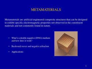
Introduction • Deisng of bulk metamaterials with negative parameters • A combination of unit cells of small electrical size at frequency of interest • Periodicity • A system of metallic wire and/or plates is used to obtain negative dielectric permittivity. • A system of split ring resonators (SRRs) is used to obtain negative magnetic permeability. 3
Scaling Plasmas at Microwave frequency • Simulation of plasmas at microwave frequencies • Became an active field of research during 1960s • Simulation of radio-communications with spaceships during transit through the ionosphere • Modeling of plasma: Systems of metallic wires [1] • Plasmas • Exhibit negative dielectric permittivity below plasma frequency • Artificial media with negative dielectric permittivity[2] [1] W. Rotman “Plasma simulation by artificial dielectrics and parallel-plate media.” IRE Trans. Antennas Propag., vol. 10, pp. 82–95, 1962 [2] J. B. Pendry, A. J. Holden, W. J. Stewart, and I. Youngs “Extremely low frequency plasmons in metallic mesostructures.” Phys. Rev. Lett., vol. 76, pp. 4773–4776, 1996 4
Metallic Waveguide and Plates as 1-D and 2-D Plasmas • Consider a hollow rectangular waveguide (TE mode) • Cutoff frequency • Wave impedance • Propagation constant • Continuous media relations A rectangular waveguide 1-D plasma with effective dielectric constant Parallel metallic plates 2-D plasma with effective dielectric constant 5
Wire Media • If the period of the wire mesh is smaller than the free-space wavelength, it should be approximately equivalent to the bunch of waveguides. • Consider a TEM transmission line loaded by metallic post • Plasma frequency • Approximation • The cutoff frequency of waveguide bunch • More accurate determination 6
Spatial Dispersion in Wire Media • Consider a set of periodic parallel infinite wires • For TEM waves propagating perpendicular to the wires and polarized with magnetic field also perpendicular to the wires • Dependence on kz • Spatial dispersion is expected to appear when the unit cell size is not small with regard to the wavelength. 7
Synthesis of Negative Magnetic Permeability • Diamagnetism • Current would be induced in the closed circuits under the effect of an external time-varying magnetic field. • The secondary magnetic flux created by the induced current would be opposite to that created by the external fields. • Closed metallic ring • Self-inductance of a perfect conducting ring 8
Synthesis of Negative Magnetic Permeability • It does not seen possible to obtain an effective negative permeability from the closed metallic ring. ( , ) • Capacitive loaded metallic loop • Magnetic polarizability of a closed loop can be enhanced by loaded the loop with a capacitor. • Show a negative permeability just above the resonant frequency 9
Analysis of Edge-Coupled SRR • EC-SRR • Initially proposed by Pendry [3] • Resonant frequency [3] J. B. Pendry, A. J. Holden, D. J. Robbins, and W. J. Stewart “Magnetism from conductors and enhanced nonlinear phenomena.” IEEE Trans. Microwave Theory Tech., vol. 47, pp. 2075–2084, 1999 10
Analysis of Edge-Coupled SRR • EC-SRR • Cross-polarizabilities • Unwanted effect : bianisotropy [19] R. Marque´s, F. Mesa, J. Martel, and F. Medina “Comparative analysis of edge and broadside coupled split ring resonators for metamaterial design. Theory and experiment.” IEEE Trans. Antennas Propag., vol. 51, pp. 2572–2581, 2003. 11
Analysis of Edge-Coupled SRR • The frequency of resonance of an EC-SRR can be measured by placing the EC-SRR inside a rectangular waveguide and measuring the transmission coefficient. Electric and magnetic excitation magnetic excitation electric excitation no excitation 12
Other SRR Designs • Broadside-coupled SRR (BC-SRR) • Avoid the EC-SRR bianisotropy • Inversion symmetry • Additional advantage of much smaller electrical length • The capacitance for the BC-SRR approximately corresponds to a parallel plate capacitor. • Thin substrate of high permeability can be used. 13
Other SRR Designs • Broadside-coupled SRR (BC-SRR) 14
Other SRR Designs • Nonbianisotropy SRR (NB-SRR) • Avoid EC-SRR bianisotropy • Inversion symmetry • Keep a uniplanar design • Resonant frequency 15
Other SRR Designs • Double-split SRR (2-SRR) • Avoid EC-SRR bianisotropy • Inversion symmetry • The total capacitance of the circuit is four times smaller than for the conventional EC-SRR. • Resonant frequency: twice the frequency of resonance of an EC-SRR • Larger electrical size at resonance 16
Other SRR Designs • Spirals • Resonant frequency: half the frequency of resonance of an EC-SRR • Smaller electrical size at resonance • Present some degree of bianisotropy 17 [25] R. Marque´s, J. D. Baena, J. Martel, F. Medina, F. Falcone, M. Sorolla, and F. Martin “Novel small resonant electromagnetic particles for metamaterial and filter design.” Proc. ICEAA’03, pp. 439–442, Torino, Italy, 2003
Constitutive Relationship for Bulk SRR Metamaterials • Effective constitutive parameters • The only necessary condition is that the size of the unit cell must be smaller than the wavelength. 18
Constitutive Relationship for Bulk SRR Metamaterials • Zero-order appoximation • Ignore couplings between adjacent elements • A rough approximation 19
Constitutive Relationship for Bulk SRR Metamaterials • Lorentz appoximation • couplings between adjacent elements are considered in a rather simple way (Lorentz local field theory) • Better approximation Array of BC-SRR 20 Array of EC-SRR
Higher-Order Resonances in SRRs • Current distribution : symmetry or antisymmetry Resonance of NB-SRR Resonance of EC-SRR 21
SRR-Based Left-Handed Metamaterials • 1-D SRR-based left-handed metamaterials • Negative permittivity of the wire system • Negative permeability of the SRR system [4] D. R. Smith, W. J. Padilla, D. C. Vier, S. C. Nemat-Nasser, and S. Schultz “Composite medium with simultaneously negative permeability and permittivity.” Phys. Rev. Lett., vol. 84, pp. 4184–4187, 2000. 22
SRR-Based Left-Handed Metamaterials • 1-D SRR-based left-handed metamaterials • A single row of SRRs is placed inside a cutoff square waveguide • Negative permittivity: the cutoff waveguide • Negative permeability: EC-SRR 23 [46] R. Marque´s, J. Martel, F. Mesa, and F. Medina “Left-handed-media simulation and transmission of EM waves in subwavelength split-ring-resonator-loaded metallic waveguides.” Phys. Rev. Lett., vol. 89, paper 183901, 2002
SRR-Based Left-Handed Metamaterials • 1-D SRR-based left-handed metamaterials • Two hollow waveguides (one above and the other below cutoff) are loaded by equispaced BC-SRRs • Passband : narrow waveguide • Stopband : wider waveguide [51] J. D. Baena, R. Marque´s, J. Martel, and F. Medina “Experimental results on metamaterial simulation using SRR-loaded waveguides.” Proc. IEEE-AP/S Int. Symp. on Antennas and Propagation, pp. 106–109, 2003 24
SRR-Based Left-Handed Metamaterials • 2-D SRR-based left-handed metamaterials • An orthogonal arrangement of dielectric circuit boards with EC-SRRs and metallic strips printed on each side • Negative permittivity : metallic strips • Negative permeability : EC-SRRs [50] R. Marque´s, J. Martel, F. Mesa, and F. Medina “A new 2-D isotropic left-handed metamaterial design: theory and experiment.” Microwave Opt. Tech. Lett., vol. 35, pp. 405–408, 2002. [52] R. A. Shelby, D. R. Smith, S. C. Nemat-Nasser, and S. Schultz “Microwave transmission through a two-dimensional, isotropic, left-handed metamaterial.” Appl. Phys. Lett., vol. 78, pp. 489–491, 2001 25
SRR-Based Left-Handed Metamaterials • Superposition • Systems providing negative permittivity and negative permeability should be placed in the way that the interaction between its elements through its quasistatic fields is minimized. 26