Download
1 / 20
200 likes | 337 Views
A Random Access Scan Architecture to Reduce Hardware Overhead. Anand S. Mudlapur Vishwani D. Agrawal Adit D. Singh. Dept. of Electrical Engineering Auburn University, AL – 36849 USA. Motivation for This Work.

E N D
A Random Access Scan Architecture to Reduce Hardware Overhead Anand S. Mudlapur Vishwani D. Agrawal Adit D. Singh Dept. of Electrical Engineering Auburn University, AL – 36849 USA
Motivation for This Work • Serial scan (SS) test sequence lengths and power consumption are increasing rapidly. • Reduction of test power and test time are complimentary objectives in serial scan. • Scope of increasing delay fault coverage is limited in serial scan. • In spite of the three advantages (test time, power, and delay fault coverage) random access scan (RAS) is not popular due to high overhead.
Outline • Introduction • Review of our “toggle” Flip-Flop design • Highlight the uniqueness and feasibility of our design due to the reduction of two global signals • Results on ISCAS Benchmark Circuits • Conclusion
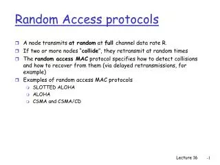
Introduction • Random Access Scan (RAS) offers a single solution to the problems faced by serial scan (SS): • Each RAS cell is uniquely addressable for read and write. • RAS reduces test application time and test power which are otherwise complimentary objectives. • Previous and current publications on RAS: • Ando, COMPCON-80 • Wagner, COMPCON-83 • Ito, DAC-90 • Baik et al., VLSI Design-04, ITC-05, ATS-05, VLSIDesign-06 • Mudlapur et al., VDAT-05 • Disadvantage: High routing overhead – test control, address and scan-in signals must be routed to all flip-flops.
Contributions of Present Work • Eliminate scan-in signal from circuit by using a toggling RAS flip-flop. • Eliminate routing of test control signal to flip-flops. • Provide a new scan-out architecture: • A hierarchical scan-out bus • An option of multi-cycle scan-out
Serial Scan (SS) Combinational Circuit PI PO Scan-in Scan-out FF FF FF Test control (TC) Example: Consider a circuit with 5,000 FFs and 10,000 combinational test vectors Total test cycles = 5,000 x 10,000 + 10,000 + 5,000 =50,015,000
Random Access Scan (RAS) Combinational Circuit PI PO Address Inputs FF FF FF Scan-out bus Decoder Scan-in These signals are eliminated in our design TC During every test, only a subset of all Flip-flops needs to be set and observed for targeted faults
The “Toggle” RAS Flip-Flop Combinational Logic 1 M S To Output BUS M U X Combinational Logic Data 0 Clock Output BUS Control x y RAS-FF √nff Lines √nff Lines Row Decoder Column Decoder Address (log2nff)
Toggle Flip-Flop Operation (contd.) Unaddressed FFs Addressed FF RAS FF 0 RAS FF 1 RAS FF 1 RAS FF 0 Decoded address lines
Macro Level Idea of Signals to RAS-FF 4-to-1 Scan-out Macrocell RAS FF11 RAS FF11 RAS FF12 RAS FF12 RAS FF13 RAS FF13 RAS FF14 RAS FF14 x1 From 3 Other RASClusters RAS FF21 RAS FF22 RAS FF22 RAS FF23 RAS FF24 } x2 RAS FF31 RAS FF32 RAS FF33 RAS FF34 x3 RAS FF41 RAS FF42 RAS FF43 RAS FF44 To Next Level x4 y1 y2 y3 y4
Scan-out Macrocell • A 4x4 block scan-out data flow and control logic • Two D-FFs may be inserted at the outputs of macrocell for multi-cycle scan-out. Data Bus From 4 RAS FFs To Next Level Output BUS { Control Signal to Next Level BUS Control From 4 RAS FFs
Routing of Decoder Signals in RAS Address (log2 √nff) Flip-Flops Placed on a Grid Structure R O W D E C O D E R Address (log2 √nff) COLUMN DECODER
Gate Area Overhead Gate area overhead of Serial Scan = Gate area overhead of Random Access Scan = where nff – Number of Flip-Flops ng – Number of Gates Assumption: D-FF contains 10 logic gates.
Gate Area Overhead (Examples) 1. A circuit with 100,000 gates and 5,000 FFs Gate overhead of serial scan = 13.3 % Gate overhead of RAS = 20.0 % 2. A circuit with 500,000 gates and 5,000 FFs Gate overhead of serial scan = 3.6 % Gate overhead of RAS = 5.5 %
Overhead in Terms of Transistors Gate area overhead of Serial Scan = Gate area overhead of Random Access Scan = Synthesis performed on SUN ULTRA 5 Machine RAS has 16 transistors more than SS Flip-Flop
Case Study on an Industrial Circuit • A case study on an industry circuit was performed at Texas Instruments India Pvt. Ltd. • The preliminary results were as follows: • The gate area overhead of RAS for a chip with ~5500 Flip-Flops and ~100,000 NAND equivalent gates was of the order of 18 % • 75 % reduction in test time was observed. A speed-up of up to 10X could be achieved using special heuristics • An approximate estimate of the routing and area overhead of RAS after physical layout was estimated as 10.4 %
Conclusion • New design of a “Toggle” Flip-Flop reduces the RAS routing overhead. • Proposed RAS architecture with new FF has several other advantages: • Algorithmic minimization reduces test cycles by 60%. • Power dissipation during test is reduced by 99%. • A novel RAS scan-out method presented. • For details on “Toggle” Flip-Flop, see Mudlapur et al., VDAT-05.