Download
1 / 63
700 likes | 990 Views
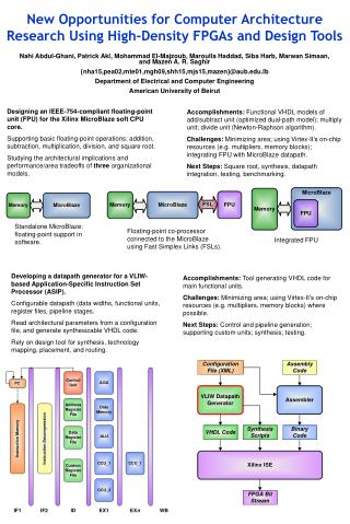
Tools for synthesis and implementation using Xilinx FPGAs. Synthesis Toolflow. HDL Designer. Design. VHDL code. Synplify Pro. XST. Leonardo Spectrum. Synthesis. Netlist. Implementation. ISE Project Navigator. Bitstream. Synthesis stages. Technology independent. Technology

E N D
Synthesis Toolflow HDL Designer Design VHDL code Synplify Pro XST Leonardo Spectrum Synthesis Netlist Implementation ISE Project Navigator Bitstream
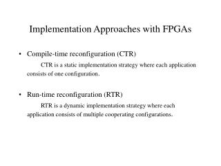
Synthesis stages Technology independent Technology dependent Compile Map Place & Route Implement High level synthesis Low level synthesis • Code analysis • - Derivation of main logic constructions • Technology independent optimization • Creation of “RTL View” • Mapping of extracted logic structures to device primitives • Technology dependent optimization • Application of “synthesis constraints” • Netlist generation • Creation of “Technology View” • Placement of generated netlist onto the device • Choosing best interconnect structure for the placed design • Application of “physical constraints” • Bitstream generation • Burning device
Synplify Pro Leonardo Spectrum Xilinx Synthesis Tools Synthesis stages Technology independent Technology dependent Compile Map Place & Route Implement High level synthesis Low level synthesis
Why we need third-side synthesis tool? • Support of larger VHDL subset • More and better optimizations • More stable synthesis • Control and management of synthesis process more user-friendly and simpler • Can be used for different technologies • Possibility of working with number of revisions in parallel • Advanced synthesis techniques • And more …
Main Topics • Lecture schedule: • Introduction to synthesis tools (Synplify and Leonardo) • Environments, constraints, timing analysis, optimizations • Introduction to Place & Route tools • Environments, pin assignment, timing information extraction • (Advanced analysis tools for FPGAs) • Using IMPACT – burning tool • Timing simulation
Introduction to synthesis Synplify Pro synthesis tool
Tool invocation • Invocation of Synplify Pro performed by double click on “Synplify PRO flow” in “Team tasks” or by pressing button in toolbar Synplify Pro invocation button Synplify Pro invocation link
Tool tuning • Working directory for Synplify is one defined in “Downstream” in HDL Designer • For each revision new directory is created and all Synplify-generated files are placed there • In case of using CoreGen, netlist generated by Coregen placed in Synplify working directory and not in appropriate revision directory. Copy it to revision directory • To avoid errors caused by embedded configurations, make them standalone by:
Synplify Pro main window Start synthesis Status line Working with files Window with source files Window with result files Working with revisions Main optimization modes Messages, warnings and errors Watch window
Understanding list of source files • If you have also Verilog files, separate directory will be created • In such case, main block of the design must be defined in another place If you use package(s), put it first in the list of files The main entity should be last in the list of files Number of revision (version)
Compilation process • Compilation is the first stage of synthesis process • There is a possibility to invoke compilation only (without mapping) by choosing “Run->Compile only” or pressing F7 • After compilation Synplify main window looks like this: Show RTL view Some files were generated
Understanding report file • All errors, warnings and notes reported during compilation, are written to “.srr” file • This file can be viewed by double click on its name in right window or pressing “View Log” button on the left side of the main window Crossprobing makes possible viewing problematic code by simple double click on errror/warning/note message Each error message started from @E and colored to red Each warning message started from @W and colored to violet Each note message sarted from @N and colored to blue
Understanding RTL view • RTL view can be opened by pressing or double click on “.srs” file The group of buttons is useful in “RTL view” window General logic structures can be recognized on RTL view comparator incrementer MUX גדול
Crossporbing between RTL view and code • Each port, net or block can be chosen by mouse click from the browser or directly from the RTL View By double-clicking on the element its source code can be seen: Reverse crossprobing is also possible: if section of code is marked, appropriate element of RTL View is marked too:
Understanding FSM Viewer • Crossprobing is possible between graphical representation of FSM and its states / transactions list Synplify Pro has feature to show state machines in graphic form (like HDL Designer). The feature is invocated by indicating “V” for “FSM Compiler” option Initial states Coding of states after compilation Coding of states after mapping
Mapping process • Compilation of design is not enough – to complete high level synthesis we need to perform also mapping • Mapping is technology dependent stage of synthesis • During mapping, excluding mapping itself, are performed the next processes: • Application of “synthesis constraints” • Generation of netlist • Initial timing analysis • Generation of “Technology View” Synthesis constraints To place & route Compilation HDL source files Compiled (RTL) netlist Mapping Mapped netlist (edif) RTL view Technology view Post map timing analysis
Defining device parameters All mapping parameters defined via “implementation options” window The window is opened by pressing button or by double-click on current revision The first step is choosing device for implementation Device-specific mapping options can apply different optimizations Stand on specific option and press F1 to learn more about it
Defining compilation optimizations Compilation optimizations can be defined in “Options” tab The same optimizations can be invoked from the main Synplify window
Defining constraint files to be applied Global frequency and constraint files can be defined in the next tab “Constraints” (we will see constraint files later)
Defining result files • Location of result files created after mapping process can be defined in the tab “Implementation results” • Additional files can be created: • Post-map netlist in HDL format for post-map timing simulation • Physical constraints file for P&R tools Important note: to prevent problems with low-level sythesis tools, the name of result netlist (edif file) should be similar to the name of the top design entity Post map netlist in HDL format P&R constraint file
Timing report definitions Timing report form can be configured by specifying number of reported critical paths or/and start/end points
Synthesis constraints specification - SCOPE SCOPE (Synthesis Constraint Optimization Environment) is graphical tool for defining different (mainly timing) constraints The output of SCOPE is the synthesis constraint file (“.sdc”) which is attached to RTL netlist and applied during mapping stage SCOPE is invoked by pressing button or by specifying File->New->Constaint File Main window of SCOPE divided to tabs by constraint types
Types of synthesis constraints • The groups of constraints are: • Clocks – defining design clocks’ form and frequency, groups of clocks, there is possibility to define part of period intended to routing delay • Clock to clock – defining relations between clocks • Input / output delays – defining propagation delays of input (Input port -> FF) or output (FF -> Output port) paths • Registers – defining setup times and propagation delays of FFs • Paths constraints • Multi-cycle – paths between FFs in which signal is allowed to be propagated in more than one clock • False – paths which is not required to be analyzed • Max-delay – paths constrained to certain delay value • Attributes – additional (non-timing) constraints • Black box definitions • Object pruning prevention • Excluding code for synthesis • And more …
Mapping invocation Mapping (including compilation) is invocated by pressing F8 , choosing “Run->Synthesize” or by pressing Showing Technology View Number of files were created Errors and warnings can appear
Understanding of Technology View Technology view is mapped RTL view. It can be seen by pressing button or by double-click on “.srm” file As in case of “RTL View”, buttons can be used here Two additional buttons are enabled: - show critical path - open timing analyst Pay attention: technology view is usually large and presented on number of sheets Technology view is presented using device primitives Ports, nets and blocks browser
Viewing critical path Critical path can be viewed by pressing on Slack and delay values are written near each component of the path
Timing Analyst Timing analyst opened by pressing on Timing analyst gives a possibility to analyze different paths in the design Timing analyst can be opened only from Technology View
Timing report • Timing report is part of general report file “.srr” • Do search of “START OF TIMING REPORT” in “.srr” file to get it • Next things can be found in this report: • General design information – name, included constraint files, required frequency, required number of critical paths to be reported • Performance summary – achieved frequency, worst slack • Clock relationship – table with rise to rise, rise to fall, fall to rise and fall to fall delays for each pair of clock groups • Interface information – standing in requirements for input / output delays • Detailed report for each clock group of the design, including: • Table with all most critical path for this clock group • Table with all start / end points for critical paths for this clock group • Separate table of signal propagation for each critical path
Working with number of revisions • Synplify gives a possibility to create number of revisions of the design, to synthesize them and compare. The most used options are: • Creation of new revision of the same design with the same constraints but for another technology • Creation of new revision of the same design with different constraints for another technology • New revision can be created by pressing on or by choosing “Project -> New Implementation” • New revision automatically accepts new revision number • Current revision is marked by green arrow • All revisions can be synthesized by choosing “Run->Run All Implementations”
Introduction to synthesis Leonardo Spectrum synthesis tool briefly
Tool invocation • Invocation of Leonardo Spectrum performed by double click on “Leonardo Spectrum flow” in “Team tasks” or by pressing button in toolbar Leonardo Spectrum invocation button Leonardo Spectrum invocation link
Tool invocation • The window for “fast start” is opened after invocation:
Leonardo definitions • There are two types of menus: • Quick setup – perform synthesis defining minimal set of options • Advanced flow tab – this tab includes options to define constraints, form of reports and invocation of P&R tools • Switching between two menus perfomed by:
Quick setup window • There is quick setup window:
Advanced flow tab • Advanced flow tab facilitates synthesis in steps: In addition there is also “Synthesis Wizard”, which passes via all above tabs one-by-one
High-level synthesis – conclusions • To obtain good synthesis results, always follow the next rules: • Write understandable HDL code. Think hardware, not software! • Analyze report file after compilation and after mapping: • - did you mean to make RAM here? • - does this register really redundant? • - why black box is created? • Especially pay attention to recognized clocks and generated latches • Use FSM Compiler to analyze derived FSM and compare them to ones drawn in HDL designer • Analyze inserted buffers in Technology View • Apply optimizations carefully • Use synthesis constraints to tune the design and estimate timing • Follow file naming conventions to avoid problems in low-level synthesis tools
Introduction to place and route tools Xilinx Project Navigator P&R tool
Reminder - synthesis stages Technology independent Technology dependent WE ARE HERE Compile Map Place & Route Implement High level synthesis Low level synthesis • Code analysis • - Derivation of main logic constructions • Technology independent optimization • Creation of “RTL View” • Mapping of extracted logic structures to device primitives • Technology dependent optimization • Application of “synthesis constraints” • Netlist generation • Creation of “Technology View” • Placement of generated netlist onto the device • Choosing best interconnect structure for the placed design • Application of “physical constraints” • Bitstream generation • Burning device
Tool invocation • From Synplify: From Leonardo:
But, there is a problem… • When running from Synplify: • ISE project is created, but Project Navigator is not opened… • When running from Leonardo: • Project Navigator is opened, but project is not created… • So, if you use Synplify: • Try to run Project Navigator (it will create the project), and after that invoke tool from Windows • If you use Leonardo: • Open Directly Project Navigator from the Windows
Project Navigator main window Source files Results window Synthesis processes Log window – errors, warnings and notes
Creation of new project • If you work with Leonardo, you have to create new project firstly • New Project is created by “File->New Project” Project directory not necessary have to be output directory of high-level synthesis tool EDIF must be chosen as top-level module type After choosing press next
Creation of new project • EDIF file created after high-level synthesis should be entered as input design • All netlists created by external tools (such as CoreGen) should be placed in the project directory together with main netlist If you want your netlist will not be affected by high-level resynthesis, specify “copy input design to the project directory” (relevant if your project directory differs from output directory of high-level synthesis tool) We will discuss further the constraint file Press next
Creation of new project • Verify that you use right device and “Modelsim “ simulator Press “Next” and then “Finish”
Opening existing project • Open existing project (when working with Synplify) by: • “File -> Open Project…” … and further choosing “.npl” file
Understanding project view • After creation or opening, design file(s) (netlist) displayed in the left top window • Possible processes displayed in the left bottom window • Process can be invoked by double-clicking on its name • When you invoke the process, the tool performs check and invokes previous processes if needed • But: • Before place & route starts, we have to define physical constraints file
Physical constraints file • Reminder – toolflow: Synthesis constraints Physical constraints Compiled (RTL) netlist Mapping Mapped netlist (edif) Place & route Placed and routed netlist (ncd) Bitstream (bit) Technology view Post map timing analysis Routed design view Post P&R timing analysis • Physical constraints file (“.ucf”) must me provided to perform Place & Route in the right way • This file is necessary for pin assignment, because it attaches physical device pins to design external ports (in contrast with synthesis constraints file that is not necessary to produce right implementation)