Statistical Parametric Mapping
Statistical Parametric Mapping. Lecture 6 - Chapter 4 Ultra-Fast fMRI. Textbook : Functional MRI an introduction to methods , Peter Jezzard, Paul Matthews, and Stephen Smith. Many thanks to those that share their MRI slides online. 0.025. T2* r =80ms. 0.020. 70ms. 60ms. 0.015.


Statistical Parametric Mapping
E N D
Presentation Transcript
Statistical Parametric Mapping Lecture 6 - Chapter 4 Ultra-Fast fMRI Textbook: Functional MRI an introduction to methods, Peter Jezzard, Paul Matthews, and Stephen Smith Many thanks to those that share their MRI slides online
0.025 T2*r=80ms 0.020 70ms 60ms 0.015 Signal, arb 50ms 0.010 40ms 30ms 0.005 20ms 10ms 0.000 0 50 100 150 TE, ms Echo Time Optimization TEopt = optimal TE for BOLD contrast lies between T2*a and T2*r R2*a = R2* relaxation rate during activation (1/T2*a) R2*r = R2* relaxation rate during rest (1/T2*r) Fig. 4.1 BOLD response as a function of TE for different values of T2*r. Note that TEopt ~ T2* and that BOLD response increases with increasing T2*r.
Effects of Field Homogeneity R2* = R2 + R2mi +R2ma • R2 = transverse relaxation rate due to spin-spin interactions and diffusion through microscopic gradients • R2mi = transverse relaxation rate due to microscopic changes, i.e. deoxyhemoglobin • R2ma = transverse relaxation rate due to macroscopic field inhomogeneity R2*a is relaxation rate during activation R2*r is relaxation rate at rest
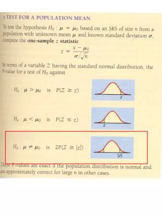
4000 1.9mm 3.8mm 3000 5.9mm number of voxels 2000 1000 0 0 50 100 150 T2*, ms Effects of Field Homogeneity Fig. 4.2 Change in histogram of T2* for thick slab through brain with changing slice thickness. Note broadening of distribution with increasing thickness with shift toward shorter T2*.
4x4x4 mm3 2x2x2 mm3 Spin Echo Gradient Echo EPI Fig. 4.3 EPI obtained with TE= 60 and TR=3000 msec and 63 and 95 ky lines. Note recovery of signal loss in d vs c and ghosting in c.
0.2 0.1 0.0 navigator phase, degrees -0.1 -0.2 -0.3 0 500 1000 1500 navigator index Intra-scan Motion Signal Fig. 4.4 Phase fluctuations at center of k-space over 42 seconds. Spikes are due to cardiac cycles and slower periodic signal due to respiratory cycles. Why would phase advance and retard?
r.f. TE readout window rephase dephase read gradient dephase gradient echo Fig. 4.5 Gradient echo (GE) echo forms at center of readout window where area under rephasing gradient = area of dephasing gradient. Unlike spin echo dephasing is due to spatial difference in Larmor frequencies during application of gradients. First half of readout window is rephasing and second half is dephasing again. This process repeats at the center of readout window for each ky line in k-space for EPI. For EPI where is the readout signal largest?
0.10 White matter Grey matter 0.08 0.06 Signal (fraction of M0) 0.04 0.02 0.00 0 15 30 45 60 75 90 Flip angle (degrees) Fig. 4.6 Graphical determination of optimal TE for GM and WM signals for multishot GE pulse sequence such as FLASH. Useful for 3D high-resolution images.
a) b) RF Slice Read Phase Read Phase n n-1 n-1 1 n 2 2 1 Fig. 4.7 GE EPI pulse sequence and k-space organization of samples. What flip angle is used for EPI?
SE GE EPI GE (FLASH) SE EPI TE=60 msec TE=120 msec Fig. 4.8 Half Fourier (k-space) images. Central 20 percent of ky portion of k-space used for estimating phase correction during conjugation (replacing missing + ky data with acquired -ky data). Note ghosting in B in phase encode direction.
Effect of system parameters on EPI images for fixed field of view. Table 4.1 from text. * actual resolution increase less than expected due to smoothing effect of signal decay.
fMRI methods for reduced k-space coverage Keyhole acquire full k-space as reference acquire reduced low-frequency k-space fMRI study fill in missing k-space from reference Half-Fourier acquire 50-60% of k-space starting at highest ky theoretical symmetry used to fill in missing ky
fMRI methods for reduced k-space coverage Sensitivity encoding (SENSE) Multiple RF coils with independent signal for each (parallel imaging) Calibration maps from full k-space each coil part of k-space 2X improvement EPI, 4X for GE UNFOLD Acquire k-space in sequential time segments time 1 acquire lines 1, 5, 9, 13 ... time 2 acquire lines 2, 6, 10, 14 ... time 3 acquire lines 3, 7, 11, 15 ... time 4 acquire lines 4, 8, 12, 16 ... reorder into k-space 4x faster per segment reduces inter echo distortions