Download
1 / 28
280 likes | 303 Views
Learn about LHC machine protection against failures, beam interlocks, and collimation systems. Overview of beam dump blocks, injection, and failure categories. Presentation by Jörg Wenninger.

E N D
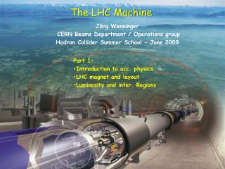
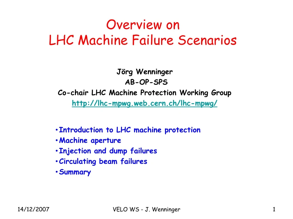
Overview on LHC Machine Failure Scenarios JörgWenninger AB-OP-SPS Co-chair LHC Machine Protection Working Group http://lhc-mpwg.web.cern.ch/lhc-mpwg/ • Introduction to LHC machine protection • Machine aperture • Injection and dump failures • Circulating beam failures • Summary VELO WS - J. Wenninger
LHC Machine Protection system • The LHC machine protection system includes all systems required to safely operate the magnets and the beams. The system is subdivided into: • Powering interlock system that protects against uncontrolled release against the energy stored in the magnets (> 10 GJ). This system is required to power the magnets. It is commissioned together with the magnets (already started). • This system is based on PLCs with typical reaction times of ~4 ms, less for a few critical circuits. • Beam interlock system that protects the LHC equipment against uncontrolled release of the energy stored in the beams (0.35 GJ). • The BIS is a VME based system with reactions times of ~ms. • Maximum time between dump request and last proton out ~270 ms. • The MPS has more than 10’000 interlocks, and in many cases sub-systems overlap in their protection. In particular the powering interlock system, which includes the magnet quench protection system, provides in many cases redundancy for ‘pure’ beam interlocks. VELO WS - J. Wenninger
Collimation system • A multi-stage halo cleaning (collimation) system has been designed to protect the LHC magnets from beam induced quenches. • Halo particles are first scattered by the primary collimator (closest to the beam). The scattered particles (forming the secondary halo) are absorbed by the secondary collimators, or scattered to form the tertiary halo. • More than 100 collimators jaws are needed for the nominal LHC beam. • Primary and secondary collimators are made of Carbon to survive severe beam impacts ! • the collimators have an key role for protection as they define the aperture. • contrary to TEVATRON and HERA the LHC cannot be operated without collimatorsas soon as ~few permill of the nominal beam intensity is stored ! Experiment Protection devices Primary collimator Secondary collimators Tertiary collimators Triplet magnets Absorbers Tertiary halo hadronic showers Primary halo particle Secondary halo + hadronic showers Beam VELO WS - J. Wenninger
LHC Layout IR3, IR6 and IR7 are devoted to protection and collimation ! Beam dump blocks IR5:CMS experiment IR4: Radio frequency acceleration IR6: Beam dumping system IR3: Momentum Collimation (normal conducting magnets) IR7: Collimation (normal conducting magnets) IR8: LHC-B experiment IR2: ALICE experiment IR1: ATLAS experiment Injection Injection VELO WS - J. Wenninger Experiments-Machine WS / June 07 4
Failure categories In the event a failureor unacceptable beam lifetime, the beammust bedumpedimmediately and safely into thebeam dump block. Two main classes for failures (with more subtle sub-classes): • Passive protection • - Failure prevention (high reliability systems). • Intercept beam with collimators and absorber blocks. • Active protection systems have no time to react ! Beam loss over a single turn during injection, beam dump or any other fast ‘kick’. Active Protection - Failure detection (by beam and/or equipment monitoring) with fast reaction time (< 1 ms). - Fire beam dumping system Beam loss over multiple turns due to many types of failures. Fastest failures >= ~ 10-ish turns VELO WS - J. Wenninger
‘Properties’ of global failures • Almost all perturbations due to failures (typically magnet powering, an injection or dump failure) affect the entire machine. • To first order the amplitude of the perturbation at any place in the ring, is proportional to the (unperturbed) beam size and to a phase factor, i.e. : • Ampl. ~ scos(phase) ~ b cos(phase)b is the betatron function • >>> For failures the parameter that defines if an element is likely to be hit is not the physical distance to the beam, but the distance in units of beam size. • >>> Since at the LHC the collimators must ALWAYS define the aperture to avoid quenches of the SC magnets, one of the collimators is always the first elements that is hit by the beam. This is confirmed by all simulations performed so far. VELO WS - J. Wenninger
Issues around ‘orbit bumps’ • Local orbit bumps are tools that are regularly used in rings for : • Crossing angles. • Separation of the beam at the IP • for injection & ramp. • Local aperture checks. • Etc… • A local bump may produce a large local excursions, and at injection one can reach basically any element of the machine (because the magnets are designed for 7 TeV): • Contrary to global failures, for a bump the amplitude does not scale with s !! • Even the fastest bumps take however seconds to minutes to bring the beam to the aperture, which leaves time for Loss Monitors to react and dump the beam. • Bumps are a worry for machine protection, because they commonly used and at the same time they are potentially dangerous, in particular in conjunction with an injection or dump failure. • >>> We have prepared strategies to detect undesired bumps (at least during normal physics operation) by analysis of orbit and corrector magnet data. To be tuned and validated in operation. x Corrector magnet s VELO WS - J. Wenninger
Comments on ‘stable beams’ • A common misconceptions is to believe that during the ‘Stable beams’ phase which corresponds to experiments data taking, the beam is … stable !!! • During the ~12 hours of colliding beams, one observes : • Thermal effects on warm magnets that affect beam parameters. • Orbit drifts (~ 1s equivalent over 12 hours at LHC) due to ground motion and tides. • Beam parameters drifts (tune…) due to the intensity decay. • Etc… • The changes are either corrected manually or by automated feedback (orbit drift). • The distinction between a ‘dangerous’ and a beneficial change one is usually only given by… the amplitude !! • >> Operational errors can happen during stable beams (by operators or feedbacks), but they are never worse than a failure due to power cuts ! VELO WS - J. Wenninger
Machine Aperture VELO WS - J. Wenninger
IR8 physical aperture VELO WS - J. Wenninger
Beam aperture • The standard LHC beam aperture model not only takes into account the physical aperture, it also includes mechanical tolerances, alignment errors, orbit tolerances, magnetic errors etc. • >> The net aperture after subtraction of all clearances is normalized by the beam size and expressed in ‘n1’ units, n1 being the primary collimator setting (in beam s) required to ensure that the aperture is beyond the beam halo of the secondary collimators. • Example : for a SC magnet where n1=10, it is possible to set the primary collimators to 10s before risking a quench of the magnet due to halo particles (assuming an properly setup collimation system !!). VELO WS - J. Wenninger
IR8 normalized aperture at injection • ARCs are the aperture limit (n1 ~7s). • The triplet magnets are slightly behind the ARC. • The primary collimator opening must be set ~5-6 s to protect the ‘cold’ arc aperture. • VELO is well protected … by the triplets ! Velo @ 30 mm Triplets IP8 Arcs VELO WS - J. Wenninger
Beam sizes • During the energy ramp, the beam size shrinks but the optics is not changed, and n1 scales with E. • During the betatron squeeze, the beam size decreases at the IP and increases in the triplet magnets, reducing the aperture near the IR. • >> This is due to the fact that phase space is conserved, a smaller size means more divergence and therefore a larger size in the next quadrupole (triplets). VELO WS - J. Wenninger
IR8 normalized aperture at 7 TeV Velo @ 5 mm, perfectly centered • At 5 mm from the beam, VELO remains behind the triplet aperture. • For b* = 2 m, the triplets define the apertures in IR8. Tertiary collimators are necessary to protect the triplet magnets (quench from halo and failures). For global perturbations of the beam parameters (s, orbit), VELO is always in the shadow of machine elements (Arc magnets, triplets): >> VELO is not directly affected by most global failures! VELO WS - J. Wenninger
Injection Failures VELO WS - J. Wenninger
Overview injection/extraction • Same principle for injection and extraction: • “kicker” magnets: fast rise time,muchless than one turn, large (~ mrad) angles • Septa magnets: two apertures with different magnetic fields • Injection: • Beam 1: IR2 • Beam 2: IR8 • Extraction: • Both beams in IR 6 • Injection and extraction lead to single turn failures !! VELO WS - J. Wenninger
Injection layout • Beam is coming in from the TI2 (IR2) and TI8 (IR8) transfer lines (both ~ 3km). • Injection in 2 steps: • Septum magnet (MSI) provides a horizontal deflection to bring the injected beam parallel to the circulating beam. • The kicker magnet (MKI) provides a vertical deflection to bring the injection beam on the orbit of the circulating beam. • The TDI absorber protects the downstream elements against damage from MKI failures (no kick, over voltage…). A mask (TCDD) helps to absorb the showers. • The injection and crossing angle schemes are ‘mixed’ (injection area overlaps with crossing angle) : crossing scheme changes associated to changes of the LHCb spectrometer polarity are very tricky from point of view of protection. VELO WS - J. Wenninger
TCDIH/V TCDIMOM SPS TT40/60 TI 8/2 LHC MKE MKI TED TED TDI Injection protection • Because the extraction process from SPS/injection into the LHC occurs over less than 10 ms, all elements must be in place and at their correct settings. • The transfers lines (up to MKI) are very heavily interlocked (magnet settings) and protected by collimators in the lines and in the LHC (TDI, TCLI downstream from IR2/IR8) : • >> Aim is to protect the LHC arc magnets against beam impact and beam halo. • >> Target : no beam beyond ~ 7s from nominal orbit. Transfer line collimators setting: 4.5 s VELO WS - J. Wenninger
Injection into an empty ring • Injection can be risky when a ring is empty, since one must be sure that all magnet settings are sufficiently good to avoid immediate loss. • That is why the LHC injection principle, implemented by hardware signals, is based on the following principle : • If some beam is present in a ring, the conditions for injection of high intensity are sufficiently good to avoid immediate loss of the beam over the first turns.Even if the lifetime is very poor, the beam will stay for some turns and the protection systems have time to detect losses and trigger the dump if necessary. • Injection logic: • - If beam is present (> ~ 2x10⁹ p), any beam intensity may be injected. • - If no beam is detected, the maximum intensity that can be injected is • > ~1010 p for regular operation. • > 1011 p in dedicated periods of machine studies (as required). • This scheme is presently under discussion, but it is not possible to go further down in intensity for the first injection. VELO WS - J. Wenninger
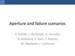
Injection failures Velo @ 30 mm • A special case of failures at injection into an EMPTY ring are (large) setting errors of separation dipoles (D1/D2) or orbit correctors close an IR: • Beam may be deflected right into the detectors. • A more likely scenario is a random setting that leads to beam impact in the triplets. • Such case can be ‘build’ for all IPs. • Cures: • Limit intensity injected into an empty ring (see previous slide). • Current surveillance of the critical magnets (by Software Interlock System). V plane Velo @ 30 mm H plane VELO WS - J. Wenninger
Extraction (dump) Failures VELO WS - J. Wenninger
Beam Dumping System Septum magnet deflecting the extracted beam MSD Beam 1 H-V kicker for painting the beam Beam Dump Block Q5L Q4L 15 kicker magnets MKD about 700 m Q4R about 500 m Q5R Beam 2 VELO WS - J. Wenninger
Requirements for a ‘clean’ dump • The extraction kicker rise time • must coincide with the 3 ms long • particle free abort gap. • The abort gap must be free of • particles (dedicated detector). • The kicker setting must match the beam energy (‘Energy Tracking’). Energy tracking errors are among the worst failures for the LHC, the system is therefore highly redundant. Abort gap VELO WS - J. Wenninger
Dump sweep: asynchronous dump • When the kicker rise does not coincide with the abort gap (‘asynchronous dump’) the bunched are swept out over all amplitudes. As protection against DAMAGE against such events (expected ~ 1 / year): • Moveable graphite absorber TCDQ (7 m), plus normal collimator (TCS) downstream from the kicker. • Tertiary collimators protect the triplets (mainly IR5) against beam leaking out of absorbers + coll. • >>> IR8 is rather well protected, since beam 1 must pass the collimation section in IR7 before reaching IR8 – should be confirmed by simulations (ongoing). VELO WS - J. Wenninger
Circulating Beam Failures VELO WS - J. Wenninger
‘Global’ failures • Since a few years a number of more or less sophisticated simulations have been performed on machine failures, including particle tracking and shower simulations with GEANT/FLUKA. • The most critical failures have been identified and for some cases, additional protection devices were added: • Fastest failures imply the normal conducting D1 separation dipoles in IR1 and IR5 that lead to beam loss on collimators after ~ 10-30 turns. • Special devices to detect fast powering failures have been developed with DESY and successfully tested in the SPS-LHC transfer lines. Such devices have been attached to the most critical magnet circuits. • All simulations so far indicate that the beams • first hit one of the collimators, • then impact on elements downstream of/close to the collimators, • and a small fraction of the beam leaks out to the Arcs & IRs, in which case it impacts frequently near the triplet magnets (depends on b* !). • LHC Beam Loss Monitor System is expected to catch such failures if the interlocks on the powering are not fast enough. VELO WS - J. Wenninger
Bump at IR8 • When VELO is in data taking position at 5 mm from the beam, the beam can be pushed to the inner edge of VELO by a specially designed orbit bump even at 7 TeV ! • Such a bump takes ~ minutes to develop and pushes some magnets to their limit. • This case is very very unlikely to happen(deliberate !), but it shows what bumps can do! • At injection a similar bump can reach much larger amplitudes but will hit the magnet apertures and not VELO (assuming it is at 30 mm). VELO WS - J. Wenninger
Summary • Beam failures may affect VELO in the following way : • During injection large settings errors of dipoles/correctors can lead to direct beam impact in the vicinity of or into VELO. Such failures will be mitigated by: • Surveillance of magnet currents (by software interlocking). • Limit on the intensity that may be injected into an empty ring (hardware signals). • With circulating beamVELO is protected from direct impact due to global failures by collimators and by the triplets, but could be affected by showers from triplets. • Local bumps can reach VELO in its data taking position, but are basically very unlikely at 7 TeV. Local bumps at injection would drive the beam into the triplet magnets or into the corrector magnets. Bump ‘failures’ will be mitigated by surveillance of corrector currents and orbit. • >> The most likely impact of failures on VELO is from showers created by beam impact on the triplet magnets (or the tertiary collimators). • Question : in case of direct impact of 1010 p near VELO at injection, would the BCMs detect the failures and react? Sensitivity/threshold? VELO WS - J. Wenninger