The LHC Machine
720 likes | 744 Views
Explore the intricate details of the Large Hadron Collider (LHC) focusing on its layout, magnets, energy levels, and beam properties along with the challenges faced and operative measures taken.

The LHC Machine
E N D
Presentation Transcript
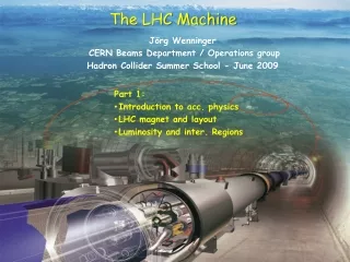
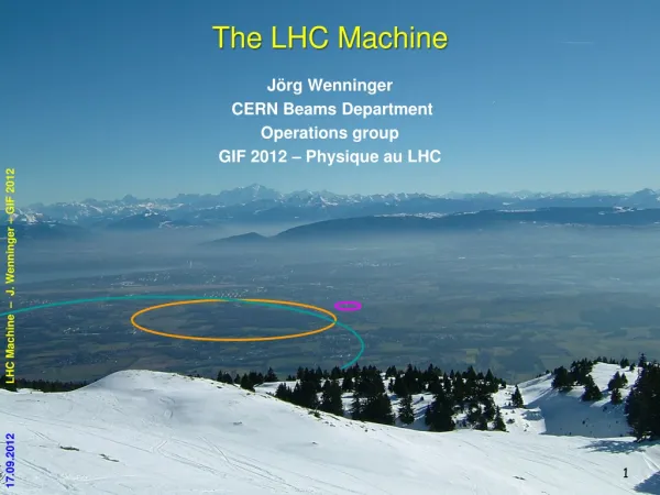
The LHC Machine JörgWenninger CERN Beams Department Operations group GIF 2012 – Physique au LHC LHC Machine – J. Wenninger – GIF 2012
Outline LHC machine High luminosity ingredients High intensity issues Performance 2010-2012 Proton-Lead LHC after long shutdown LHC Machine – J. Wenninger – GIF 2012
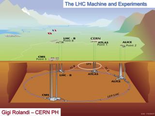
The Large Hadron Collider LHC Installed in 26.7 km LEP tunnel Depth of 70-140 m Lake of Geneva LHC ring LHC Machine – J. Wenninger – GIF 2012 CMS, Totem LHCb Control Room SPS ring ATLAS, LHCf ALICE
LHC layout and parameters RF • Total length 26.57 km, in the former LEP tunnel. • 8 arcs (sectors), ~3 km each. • 8 long straight sections (700 m each). • beams cross in 4 points. • 2-in-1 magnet design with separate vacuum chambers → p-pcollisions. LHC Machine – J. Wenninger – GIF 2012
LHC accelerator complex Beam 2 Beam 1 TI8 TI2 LHC proton path ≥ 7 seconds from source to LHC LHC Machine – J. Wenninger – GIF 2012
LHC dipole magnet • 1232 dipolemagnets. • B field 8.3 T (11.8 kA) @ 1.9 K (super-fluidHelium) • 2 magnets-in-one design : two beam tubes with an opening of 56 mm. • Operating challenges: • Dynamicfield changes at injection. • Verylowquenchlevels (~ mJ/cm3) LHC Machine – J. Wenninger – GIF 2012
Vacuum chamber • The beams circulate in two ultra-high vacuum chambers, P ~10-10 mbar. • A Copper beam screen protects the bore of the magnet from heat deposition due to image currents, synchrotron light etc from the beam. • The beam screen is cooled to T = 4-20 K. Beam screen LHC Machine – J. Wenninger – GIF 2012 Magnet bore Cooling channel (Helium)
LHC energy: the way down When Why • All main magnets commissioned for 7TeV operation before installation • Detraining found when hardware commissioning sectors in 2008 • 5 TeV poses no problem • Difficult to exceed 6 TeV • Machine wide investigations following S34 incident showed problem with joints • Waiting for new • Quench Protection System • (nQPS) 7 TeV 2002-2007 Design 12 kA 5 TeV Summer 2008 Detraining 9 kA LHC Machine – J. Wenninger – GIF 2012 Late 2008 3.5 TeV Joints Spring 2009 6 kA 1.18 TeV Nov. 2009 nQPS 2 kA 450 GeV
LHC target energy: the way up When What • Train magnets • 6.5 TeV is in reach • 7 TeV will take time • Repair joints • Complete pressure relief system • Taking a slightly higher risk • Excellent experience in 2010/11 • Commission nQPS system 7 TeV 2014/5 Training 6 TeV Good joints 2013 LHC Machine – J. Wenninger – GIF 2012 4 TeV 2012 3.5 TeV 2011 nQPS 2010 1.18 TeV 2009 450 GeV
Magnet Interconnection Melted by arc LHC Machine – J. Wenninger – GIF 2012 Dipole busbar
Collateral damage Quadrupole-dipole interconnection Quadrupole support LHC Machine – J. Wenninger – GIF 2012 Sooth clad beam vacuum chamber • Main damage area covers ~ 700 metres. • 39out of 154 main dipoles, • 14 out of 47 main quadrupoles • from the sector had to be moved to the surface for repair (16) or replacement (37).
LHC repair and consolidation 14 quadrupole magnets replaced 39 dipole magnets replaced 204 electrical inter-connections repaired Over 4km of vacuum beam tube cleaned LHC Machine – J. Wenninger – GIF 2012 New longitudinal restraining system for 50 quadrupoles Almost 900 new helium pressure release ports 6500 new detectors and 250km cables for new Quench Protection System to protect from busbar quenches Collateral damage mitigation
Luminosity figure-of-merit The event rate N for a physics process with cross-section s is proprotional to the collider Luminosity L: Design k = number of bunches = 2808 N = no. protons per bunch = 1.15×10¹¹ f = revolution frequency = 11.25 kHz s*x,s*y = beam sizes at collision point (hor./vert.) = 16 mm LHC Machine – J. Wenninger – GIF 2012 • To maximize L: • Many bunches (k) • Many protons per bunch (N) • Small beam sizes s*x,y= (b*e)1/2 • b*: beam envelope (optics) • e: beam emittance, the phase space volume occupied by the beam (constant along the ring) High beam “brillance” N/e (particles per phase space volume) Injector chain performance ! Small envelope Strong focusing ! Optics property Beam property
Stored energy • Increase with respect to existing accelerators : • A factor 2 in magnetic field • A factor 7 in beam energy • A factor 200 in stored beam energy LHC 2012 LHC Machine – J. Wenninger – GIF 2012 Damage threshold
To set the scale… A few cm long groove in a SPS vacuum chamber after the impact of ~1% of a nominal LHC beam (2 MJ) during an ‘incident’ LHC Machine – J. Wenninger – GIF 2012
Collimation 1.2 m beam • To operate at nominal performance the LHC requires a large and complex collimation system • Previous colliders used collimators mostly for experimental background conditions - the LHC can only run with collimators. • Ensure ‘cohabitation’ of: • 100’s of MJ of stored beam energy, • super-conducting magnets with quench limits of few mJ/cm3 • Almost 100 collimators and absorbers. • Alignment tolerances <0.1 mm to ensure that over 99.99% of the protons are intercepted. • Primary and secondary collimators are made of Carbon to survive large beam loss. LHC Machine – J. Wenninger – GIF 2012
Collimation system TCS6/ TCDQ σ calculated with emittance = 3.5μm TCT TCLA7 Aperture TCS7 TCP Kicked beam 5.7 σn 8.5 σn 17.7 σn 9.3 σn 15.0 σn 17.5 σn 5.7 σn 8.5 σn 17.7 σn 9.3 σn 11.8 σn 14.1 σn 4.3 σn 6.3 σn 8.3 σn 7.1 σn 9.0 σn 10.5 σn 6.0 σn 7.0 σn 10.0 σn 7.5 σn 8.3 σn 8.4 σn 2010, β*=3.5m, 3.5 TeV 2011,β*=1.0m, 3.5 TeV 2012,β*=0.6m, 4 TeV Nom, β*=0.55m, 7 TeV Primary halo beam LHC Machine – J. Wenninger – GIF 2012 Secondary halo Courtesy of R. Bruce Tertiary halo • Complex and high performance multi-stage collimation system. • Collimator position hierarchy has to be respected in order to achieve satisfactory protection and beam halo cleaning. • Excellent performance of collimation at LHC – not a single magnet was quenched from beam losses, low backgrounds.
Beam dumping system • The dump is the only LHC element capable of absorbing the nominal beam. • Beam swept over dump surface (power load). Dump block • Ultra-high reliability and fail-safe system. Dilution kickers LHC Machine – J. Wenninger – GIF 2012 700 m Extraction septum magnets Extraction kickers 30 cm
Outline • LHC machine • High luminosity ingredients • High intensity issues • Performance 2010-2012 • Proton-Lead • LHC after long shutdown LHC Machine – J. Wenninger – GIF 2012
From the basis… The luminosity formula (head-on collision,round beams): LHC Machine – J. Wenninger – GIF 2012 • f is the revolution frequency (11.25 kHz), g = E/m, • k is the number of colliding bunch pairs, • N is the bunch population, • F is a geometric (loss) factor (≤ 1) from the crossing angle, • e is the normalized emittance, b* the betatron (envelope) function at the IP, • s is the beam size at IP: (Round beams)
Interaction regions geometry • In the IRs, the beams are first combined into a single common vacuum chamber and then re-separated in the horizontal plane, • The beams move from inner to outer bore (or vice-versa), • The triplet quadrupoles are used to focus the beam at the IP. Triplet Triplet Machine geometry in H plane D2 D2 LHC Machine – J. Wenninger – GIF 2012 194 mm D1 D1 beam2 beam1 IP ~ 260 m Common vacuum chamber ~ 40 m beam2 beam1 D1,D2 : separation/recombination dipoles
Separation and crossing • To prevent undesired parasitic collisions in the region where the beams circulate in the common vacuum chamber: • Parallel separation in one plane (mostly effective at the IP), which is collapsed to 0 when the beams are colliding, • Crossing angle in the other plane. a 4 mm (450 GeV) 1.3 mm (4 TeV) LHC Machine – J. Wenninger – GIF 2012 4 TeV / 2012 ! ~ 8 mm Not to scale !
b* and beam size at IP • The focusing at the IP is defined by b*, which describes the beam envelope (optics) and which relates to the beam size s. • Note that the beam size shrinks with energy ! • b* is limited by the aperture of the tripletquadrupoles around the collision point and by the retraction margins between collimators. LHC Machine – J. Wenninger – GIF 2012 • Smaller sat the IP implies: • Larger beam divergence (phase space conservation !) • Faster beam size growth in the space from IP to first quadrupole! • Larger beam size around the IP
Limits on b* In the high luminosity IRs, the triplet quadrupoles define the machine aperture limit for squeezed beams, and b* is constrained by: • the beam envelope, • a margin between the tertiary collimators (TCT) and the triplet , • must fit in the overall collimator hierarchy • the crossing angle – separation of the beams at the parasitic encounters. LHC Machine – J. Wenninger – GIF 2012 TCT TCT Triplet Triplet ≥10.5s 9s ~ 8 mm TCT TCT=Tertiary Collimator
b* evolution LHC Machine – J. Wenninger – GIF 2012 TCT @ 9s • 1sbeam envelopes TCT @ 9s • 9sextreme beam envelopes • 1.5smargin to triplet • emittance = 3.5 mm, • b* =0.6m
Geometric luminosity factor • With the current low emittances and small b* the geometric reduction factor due to bunch length ssand crossing angle becomes significant. • Will get even stronger at 6.5-7 TeV. • Fix with ‘Crab cavities’ (maybe !) for HL-LHC. 2a LHC Machine – J. Wenninger – GIF 2012 b* = 0.6 m F = 0.81 x/y s e = 2.3 mm a = 145 mrad
Bunch filling schemes • The LHC 400 MHz Radio-Frequency system provides 35’640 possible bunch positions every 2.5 ns (0.75 m) along the LHC circumference. • A priori any of those positions could be filled with a bunch… • The smallest bunch-to-bunch distance is fixed to 25 ns: max. number of bunches is 3564 (- some space for the dump kicker beam free region). • The LHC can operate with isolated bunches or with trains of closely spaced bunches. • Startup 2010 : up to 50 isolated bunches (separation ≥ 1 ms). • Fall 2010 : 150 ns spacing - up to 368 bunches. • 2011 : start-up with 75 ns spacing, now 50 ns (1380 bunches). LHC Machine – J. Wenninger – GIF 2012 = bunch position = filled position 2.5 ns … 25 ns 27
1092 bunches with 50 ns spacing Beam 1 RMS bunch length ~ 9 cm Beam abort gap (3 ms) 6 or 12 bunch intermediate injection LHC Machine – J. Wenninger – GIF 2012 LHC circumference
Bunch spacing • 50 ns bunch spacing is used operationally since April 2011. • Progressive increase of the bunch number and the bunch intensity over 2011 and 2012 (intensity). • The 50 ns beam has the highest luminosity potential. • 25 ns beam is more difficult to operate ( see later). LHC beam parameters (SPS extraction) LHC Machine – J. Wenninger – GIF 2012
Bunch parameters 2012 • Bunch intensities when beams are brought in collisions are now > 1.5×10¹¹ p. • But we are at the limit of what can be delivered out of the PS. 1.5×10¹¹ LHC Machine – J. Wenninger – GIF 2012 Emittances are relatively stable around 2.4 mm. 2.4 450 GeV: 1.6 - 1.9 mm
Outline LHC machine High luminosity ingredients High intensity issues Performance 2010-2012 Proton-Lead LHC after long shutdown LHC Machine – J. Wenninger – GIF 2012
High intensity beam issues • With 50 ns operation and with stored intensity of ≥ 2x10¹⁴protons (1380 bunches), issues related to high intensity and tight collimators have affected LHC operation in 2011 and 2012: • Vacuum pressure increases, • Heating of elements by the beam induced fields (injection kickers, collimators, lately also synchrotron light mirrors), • Losses due to dust particles falling into the beam (UFO), • Beam losses due to tails, • Beam instabilities leading to emittance blow-up. LHC Machine – J. Wenninger – GIF 2012 • The last 2 issues had an important impact on machine efficiency in 2012, leading to a number of total beam losses. • 2012: Lost 35 fillsdue to those issues. • 2011: Only 1 filllost.
Tighter collimators • To be able to reduce b* from 1 m to 0.6 m in 2012, the collimators had to be set closer to the beams. • The primary collimator openings were reduced from ±5.7sto ±4.3s (s = rms beam size). Intensity 2011 • As a consequence, we are now very sensitive to the beam tails. • Losses in the cycle after injection have increased a lot with respect to 2011. • A lot of beam, ~ few %, in the tails (not Gaussian !!) LHC Machine – J. Wenninger – GIF 2012 <1% losses 2012 Comparison of losses between start of ramp and start of collisions Beam 2 5% losses Beam 1
Heating damage • High intensity beams may deposit large amounts of power in incorrectly shielded components. • Design, manufacturing or installation errors may lead to partial or total damage of accelerator components. • So far they have not limited, could be fixed or mitigated. LHC Machine – J. Wenninger – GIF 2012 BS BS Collimator jaw Damaged RFfingers Damaged beam screen (BS) in an injection protection device Damaged mirror of the synchrotron light telescope
Beam instabilities for pedestrians • The 50 ns high intensity beams can be seen as a complex system of coupled oscillators, • Particles oscillating within bunches (single bunch modes), • Bunches oscillating with respect to each other (coupled bunch modes), within one beam and between the 2 beams. LHC Machine – J. Wenninger – GIF 2012 Bunch n n+3 n+2 n+1 • Coherent oscillations and instabilities are driven by: • Longitudinal motion within a bunch (head-tail motion), • Fields induced in vacuum chamber elements that act back on the beam (‘impedance’, e.g. tight collimators …), • Head-on and long range interaction between the 2 beams in the common vacuum chamber regions (‘beam-beam’). • …
Beam instabilities • In 2012 instabilities have become more critical due to higher bunch intensity and tighter collimators settings. Cures: • Transverse feedback (‘damper’) that measures the oscillations and sends corrective deflections, • Non-linear magnetic fields (sextupoles, octupoles, beam-beam interaction at the collision points) that produce a frequency spread among particles: • - Particles at different amplitudes oscillate at different frequencies prevents coherent motion (‘Landau damping’). LHC Machine – J. Wenninger – GIF 2012 • Things are now ~ under control, but we are operating on the ‘edge’. • And we have more losses on beam 2 – not understood.
And what about 25 ns beams? • Between 2010 and 2012 we have reduced the bunch spacing for regular operationto 50 ns. • But the nominal 25 ns beams have not been used so far for normal operation because: • 50 ns beams provide higher peak luminosity, at the price of high pile-up, • 25 ns beams suffer much more from electron cloud effects. • estimate 10 days (scrubbing, etc) to be ready for operation. • Successful tests of 25 ns beams were performed at injection (~2000 bunches stored) and 3.5 Tev (pilot fill with 60 bunches) in 2011. • In 2012 the tests will continue in order to prepare operation with 25 ns beams at 6.5-7 TeV. LHC Machine – J. Wenninger – GIF 2012
Electron clouds • … affect high intensity beams with positive charge and closely spaced bunches. • Electrons are generated at the chamber surface by particle impacts, photons… • If the probability to emit secondary e- (SEY) is high enough, more e- are produced and accelerated by the fields of following bunches if those bunches arrive sufficiently close in time. Multiplication starts… • Electron energies are in the 10- few 100 eV range. • The cloud of e- can induces pressure rise (liberates gas from the surface) , beam instabilities and possibly overload the cryogenic system by the heat deposited on the chamber walls ! LHC Machine – J. Wenninger – GIF 2012 Bunch N+2 accelerates the e-, more multiplication… Bunch N+1 accelerates the e-, multiplication at impact Bunch N liberates an e- e- e- N+2 N+1 N ++++++ ++++++ ++++++ e-
Courtesy of G. Rumolo 2012 25 ns tests (10 July 2012) Beam 1 Beam 2 Bunch-by-bunch intensity Beam 1 LHC Machine – J. Wenninger – GIF 2012 Bunch-by-bunch intensity Beam 2
Beam scrubbing • The e-cloud can ‘cure itself’: the impact of the electrons cleans the surface (Carbon migration), reduces the electron emission probability and eventually the cloud disappears. • ‘Beam scrubbing’ consists in producing e-clouds deliberately with the beams in order to reduce the SEY until the cloud ‘disappears’. • Done at 450 GeV where fresh beams can be injected easily. • In April 2011 50 ns beams were used to ‘scrub’the vacuum chamber at 450 GeV to prepare operation at 3.5 TeV. • Further slow improvement during operation at 3.5 TeVand 4 TeV. • More scrubbing time to come for 25 ns beam. • Secondary Emission Yield (SEY) evolution in LHC arcs: LHC Machine – J. Wenninger – GIF 2012 • 2.21.7 ~1.5 1.3 Initial After 50 ns scrubbing Requirement for 25 ns operation Present
Surprise, surprise ! • Very fast beam losses (time scale of ~millisecond) in the super-conducting regionsof the LHC have been a surprise for the LHC – nicknamed UFOs (Unidentified Falling Object). If the loss is to high, the beams are dumped to avoid a magnet quench. • 2010: 18 beam dumps, • 2011: 17 beam dumps, • 2012: 13 beam dumps so far. LHC Machine – J. Wenninger – GIF 2012 • We are now certain that the UFOs are small (10’s mm) dust particles falling into the beam. • Triggered by the presence of the fields of the beam. Mechanism for removing the dust from the surface is not fully understood. Time evolution of beam loss signal
2011: Decrease from ≈10 UFOs/hour to≈2 UFOs/hour. 2012: Initially, about 2.5 times higher UFO rate compared to October 2011. UFO rate decreased since then to 2011 level. Arc UFO rate Courtesy of T. Baer No. UFOs/hour LHC Machine – J. Wenninger – GIF 2012 5836 candidate arc UFOs during stable beams since 14.04.2011. Fills with at least 1 hour stable beams are considered. Signal RS04 > 2∙10-4Gy/s.
Spatial distribution around the ring very similar in 2011 and 2012. Many UFOs around injection kickers (MKIs). Al oxide particles produced during the machining of the inner ceramic tube of those fast kicker magnets. Some arc cells with significantly increased number of UFOs. We do not know what dust is actually falling into the beam in the arc regions. Spatial UFO distribution Courtesy of T. Baer MKI MKI LHC Machine – J. Wenninger – GIF 2012
Intensity dependence and 7 TeV • The rate of events increases with beam intensity. • A large increase was observed with 25 ns beams – to be confirmed this year. UFO rate /h No bunches LHC Machine – J. Wenninger – GIF 2012 At 7 TeV: Intensity • The losses induced in the magnets by the UFOs will increase by a factor 3 (density at shower max in the magnets), • The tolerable loss will go down by a factor 5 (higher B field), • scaling the rate and amplitudes of 2012 one predicts at least one beam dump per DAY!! Could become a serious issue !!
Outline • LHC machine • High luminosity ingredients • High intensity issues • Performance 2010-2012 • Proton-Lead • LHC after long shutdown LHC Machine – J. Wenninger – GIF 2012
The LHC timeline August 2008 First Injection tests December, 2011 3.6e33, 5.6 fb-1 LHC Machine – J. Wenninger – GIF 2012 March, 2012 4 TeV June, 28 2011 1380 bunches September, 10 2008 Both beams circulating 1380 4 TeV November 29, 2009 Beams back 2008 2009 2010 2011 2012 November 2010 Ion run July 4, 2012 Higgs boson search update September, 19 2008 IncidentAccidental release of 600 MJ stored in one sector of LHC dipole magnets March 30, 2010 First collisions at 2·3.5 TeV
Evolution of parameters: 2010 to 2012 LHC Machine – J. Wenninger – GIF 2012
Operational cycle • Cycle: • Injection • Ramp • Squeeze • Collide beams • Stable physics beams • Ramp down/cycle • In 2012 a good turn around is performed in 3 hours – best ~2h 15. Beam charge(example for ions) Magnet current [A] LHC Machine – J. Wenninger – GIF 2012 • During the ‘squeeze’ phase, the betatron function at the collision points (b*) is reduced to increase the luminosity. • Cannot be done at injection – the beam is too large ! Courtesy S. Redaelli
Operational cycle http://op-webtools.web.cern.ch/op-webtools/vistar/vistars.php?usr=LHC1 LHC Machine – J. Wenninger – GIF 2012
Operational cycle Filling Beams in collision • Beams dumped LHC Machine – J. Wenninger – GIF 2012 Ramp down Flat-top adjust. and squeeze Pre-injection flat bottom Ramp up STABLE BEAMS Injection plateau