Download

1 / 29
290 likes | 403 Views
Updates on PMT deliveries, testing progress, committee formations, gain sorting proposal, base board testing, cable purchases, milestones, and gain measurement requirements.

E N D
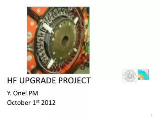
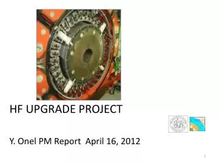
HF UPGRADE PROJECT Y. Onel PM July 23, 2012
Recent Highlights and News-I • The PMT deliveries are now completed. Testing is going well. We had a meeting with Hamamatsu regarding our reject tubes. We have shipped back about 25 PMT’s ( low gain, high dark current and black cover problems) to be tested by them. We have approved the Base Board Production. • Working on the New HV testing system and forming a committee to evaluate the RFP responses. Bulgarian new module testing is completed. Received a detailed report from German and Alexi.Both power supplies (CAEN and Bulgarian) were tested and evaluated at CERN E-pool using professional equipment and high expertise level of pool technicians. • The HV RFP and decision committee is now formed. Members are: Germain, Alexi, Ianos, S.Los, M.Miller, D.Winn from HF and Magnus and S. Lusin from CMS Coordination. The charge to this committee is written and hoping to arrange a meeting in early August. Once the decision is taken by this committee- we will report this recommendation to the PRR Committee. Magnus has accepted to be in both committees. • We have decided on the shield length- 54 mm (looks good !! the presentation by Ianos during HF meeting on May 14th ) and got confirmation by Pawel. Mike Fountain has started with the production.
Recent Highlights and News-II Gain Sorting Proposal by Ugur is now ready. -A uniform gain distribution for one HF is outlined from the foist 900 PMT sample. Other than the fringes at the edge of the sample, we can get gain uniformity within2% -EM and HAD, and 4 Quadrant separation would work if we can deliver different HV for each group (total 24 groups). -As the operation gain is decided, we can develop sorting and HV distributions for each group. We are working on the 2nd set of 900 PMT sorting. - Base Board testing on the 11 Pre-production boards are done at Iowa. We see no problems and requested to start for the production. We have shipped 6 boards to CERN last week. -Life-time results for the first 200C is reported and the results are in agreement with the Hamamatsu measurements as well as our base-line measurements. - New cable specs for the request of quotes are getting ready. -Connectors and cables for two new dark boxes were received and shipped to CERN. -First 864 PMT’s (900– spares) were delivered to CERN.
Recent Highlights and News-III There is an agreement for a new cable purchases– Thanks Chris Tully, Jeremy Mans and Pawel De Barbaro for this. There is also a strong support from Austin and Magnus on this. Decision is to purchase all ROBOX inside cables and 1/8 of 5m cables FEE and connector cables to the existing FEE and start installing these and purchase the remaining by Mid-2013 that we have all cables installed during LS1. This will enable us to go to the 2 channel readout option by LS1.5 or YETS (2014-15 ??).This means that the HF FEE design and construction will go rather fast ( att. to our Turkish and Brazilian groups) HF new front end integration was presented by Ianos to the HCAL as well as to the CMS TC. The HF Electronics Packaging as well as the agreement within HCAL that we should pursue the Winchester Cables presented by Terry Shaw. Terry Shaw and Ianos are now working on the final specs and Terry will be getting the quotes soon. Developing our “Project Org Chart” adding Brazilian Universities and ITU, Istanbul. Alberto Santoro and Gilvan-Augusto Alves are named as Co-L2’s for Brazil in our org chart. E.Gulmez BU-Istanbul is L2 for Turkey.
Milestones 2012 HF UPGRADE PROJECT MILESTONS • PMT Testing 50% Complete 1/1/2012 • Production Readiness Review 1/12/2012 • New YETS 2012 ROBOX manufactured, tested and installed in CMS 2/17/2012 • New cable purchase decision 2 or 4 channel 7/1/2012 • Start of CMS 2012 Shutdown 12/5/12 * MOVED TO 11/2/2013 • Equip ROBOX test stands at SX5 11/23/12** • Gather Miscellaneous Hardware/Equipment for in-situ HF Testing in Garages 11/23/12 ** • Install Miscellaneous Hardware/Equipment for in-situ HF Testing in Garages 12/19/12 ** • HF Plus Moved into Garages 12/21/12* • * NEW LHC and CMS dates. • ** We have to re-define these dates. HCAL INTERNAL MILESTONES • New HV system purchase decision 8/15/2012 • HF PMT characterization and testing 100% done 10/1/2012 • HF PMT's are shipped to CERN 10/15/2012 • HF PMT Boards QC testing 100% at Iowa 11/1/2012 • Start of the HF ROBOXes shipping to CERN 11/1/2012 • HF PMT's are shipped to CERN 10/15/2012
Good Gain Measurement Requirements • PMTs should be burned-in recently, keeping them on shelf for a long time months is not good!! What is the min period ?? 6 Months or a year or two years ?? • PMT should stay in dark to calm, before gain measurement. • In Iowa the PMT gain measurements are done within 1 month of their arrival from company, and PMTs are NOT exposed to high current before measurements. • So, both of these conditions are satisfied in Iowa tests.
Iowa Gain Measurement Statistical Error After eight independent gain measurements of same PMT (JA1238) our results are within 3.5% deviation. Our gain measurements are consistent !!
OLD PMT vs NEW PMT Old PMTs(idleseveral years) exhibit systematic gain loss vs Integrated Luminosity, rate of loss slowing down. New PMTs (burned in) (24 installed in Feb-2012) show no signs of gain changes so far (3mo, ~6fb-1) HCAL Operations report CMS Week June 2012 Pavel Bunin, JINR, Sudan Paramesvaran, https://indico.cern.ch/getFile.py/access?contribId=1&resId=0&materialId=slides&confId=195406
PMT Lifetime • PMT exposed to constant light intensity • Current from PMT anode integrated over time gives total charge
So what is wrong with the lifetime gains? • Our R7525 lifetime test had only measured gain after 3000 C. There were no middle gain measurements.Nucl.Instrum.Meth.A550:145-156,2005 • For R7600 were asked us to measure the gain at every possible interval. We tried!!! But gain of the PMT seemed to increase?? • The problem was “disturbed” (100 uA continuously over weeks) PMT!!! The PMT needs to calm down before the measurement!
Longer explanation of the problem, and solution…. • In the lifetime test the current through the tube is set to 100uA. This level is high so that the test can be completed in a reasonable time, but not so high as to damage the PMT (~30x HF running 50ns,pileup 40 highest eta). During the lifetime test there were breaks in the testing because it takes a very long time (goal was to reach high number of coulombs, not measure stability). Given the high current and on-off cycles one can not expect the lifetime test as performed to be an indication of stability. These conditions will exaggerate the drift of the PMT. For example there will be internal heating of the PMT. Insides are under vacuum and the internal structures + leads have poor thermal conductivity, charge stabilization. • In a linear-focused PMT, with diffused Cs as generated by "getter buttons inside the vacuum envelop for fabricating the photocathode, like the R7525, at high anode currents (~100 microA), the focused electron cloud can erode the Cs which has distilled on the CuBe-oxide dynode surfaces during fabrication (see pages 50-52 of the Burle/RCA Handbook, c.1987). The Cs enhances the secondary emission by at most ~5-10%; therefore on the last 2-3 dynodes this can be appreciable. This is fully recoverable with time under no light conditions, and the recovery accelerates by heating the tubes above ~80 degrees C. This effect is far less on the new quad-PMT, since: a) they are made by cathode transfer, and b) the dynodes are proximity focused (quasi venetian blind), so the current density (local instantaneous heating) on a dynode surface is far less (i.e. almost all the dynode surfaces are used for gain, as opposed to a few mm spot in linear-focused where the bulk of the metal surface in the dynode is used as a focus electrode), with the heat transfer larger, and c) the dynodes are made of a very different material (stainless, with a special oxide coating).
How long calming down needed ? After 3 weeks waiting After three weeks of cool-down, the gain of the lifetime PMT is virtually same as the beginning!!
Iowa vs Hamamatsu Gain Measurements • Our three gain test results for the lifetime PMT matches within 1% of the gain information provided by Hamamatsu (red dot).
Conclusion • Iowa Gain tests are valid as long as we burn in the PMTs. • During the lifetime tests we cannot measure the gain, unless we wait few weeks at every time • We will run the lifetime test without interruption, as we have done before. • Hamamatsu has now provided the life-time data for R7600. • Hamamatsu does not measure gain on their lifetime test, they measure PMT current continuously. Since we do not have a light source which sill stay stable such a long time, we cannot do that. • The terminology is important. Gain Drift (unburned or long term stored PMT’s) and Gain drop to 50% (burned PMT after the charge depletion of 3000C-our spec). • If there is a very long idle period, we have to re-burn them at least with 10 MicroA current or 20 hours with 100 MicroA as Hamamatsu states. • The aging would be necessary after an extended period of PMT storage. If 10 uA is too large for our Pt 5 system, 1 uA might be OK. However, a warm-up period is also necessary for stable PMT operation. Hamamatsu recommends a warm-up system for HF. Jeremy is working on this.
Working on the planning for 2013-14 HF upgrade will happen in at least two phases: • PMT’s will be replaced (LS1) • Rebuild readout boxes (new PMT’s, PCB’s, and new cables). • Change HV power supplies in USC. 2. Front end electronics will be replaced (eYETS?) Prefer to do this • Reconfiguration of on detector racks • Additional LV [New backend electronics already commissioned] Before, or at same time as electronics replacement: • Front end signal cables will need to be replaced • Additional fibers will need to be pulled (3.) If not already done, double the channel count to fully exploit multi-anode PMT’s. in LS1
Changes to boxes • PMT’s changed from Hamamatsu R7525 to Hamamatsu R7600-u100-M4 (four anode PMT’s) • PMT shields • Base boards • Internal support mechanics • Maybe internal cables. • HV power supplies in USC will also be changed • - Will use existing HV cabling. Depends on when we replace external cables • New PMT’s have four anodes. For LS1 the anodes will be ganged together to match the number of readout channels of our existing FE electronics. • Later (LS1.5?) when new electronics are available boxes will be reconfigured for multi-anode readout. • New design has “adapter” boards which connect cables to base boards and determines the anode configuration. • Allows easy transition to multi-anode readout, or future change of anode configuration. • Improves maintainability of readout boxes. Cable support Adapter board Base board
ROB work flow Remove boxes from both HF’s UXC • Work starts as soon as HF’s are in garages and boxes accessible. • Refurbishment will happen in SX5, HCAL alcove • Boxes will be processed in groups of “quadrants”, 9 boxes that make up 90 degrees in phi on HF. • Boxes will be remounted and commissioned by quadrants (Smallest unit due to shared HV). • Burn in and commissioning happens whenever services are available. • Off critical path. Have flexibility here RP screening Disassembly Refurbishment USC Testing Remount on HF’s UXC Testing/burn-in, commissioning Sourcing
New front end cables Lower level cable storage under floor New electronics with cabling for dual-anode readout
HF Upgrade Staging Stage 1 (LS1) • PMT replacement • Upgrade cabling to allow transition to new FEE and 2-anode readout • Use existing FE electronics. • Adapter boards in readout boxes will gang anodes • Cable Adapters at FEE crates will adapt new cabling to present electronics Stage 2 • Upgrade FE electronics for 2-anode readout and TDC • RoBox adapter boards changed for two 2-anode • Racks will be reconfigured for new FEE • Maintain the possibility to switch to four-anode readout in the future should that prove necessary.
Front end signal cables For multi-anode readout: • Cable volume will double • Existing cables must be replace due to insufficient connection density Cabling solution identified (Winchester electronics)that meets our requirements. • Connection density • Robustness • No degradation of detector performance -Consists of 3 parts: Cable for inside RoBoxes, 5m cables to FEE, and Adapters to connect to existing FEE Inside RoBox 5m Cable to FEE 24 Coax connector Adapter for Existing FEE
HF QIE Card Very Similar To HB/HE QIE Card
TDC in HF • Rising edge TDC data comes from the QIE10 – 5 or 6 bit - 390 to 780 psbin size • Falling edge comes from FPGA • Uses QIE10 discriminator output • 4 bits, one special code -1.56 ns-bin • Special code will indicate multiple pulses.
HF Card concept Dual QIE board unit 2x24 channels =48 / unit 6U crates with 1.2” module spacing.
Iowa Lifetime Tests (R7525) Sphere – 3250 C Triangle – 3000 C Before After The gain of the PMTs dropped to 60% - 50% of the initial values, with around 3000 C of charge accumulation. We will do the same for R7600.